EP9315 Enhanced Universal Platform System-on-Chip Processor EDB9315A Engineering Development Board Technical Reference Manual ©Copyright 2006 Cirrus Logic, Inc. http://www.cirrus.
EDB9315A Technical Reference Manual CORPORATE HEADQUARTERS Cirrus Logic, Inc. 2901 Via Fortuna Austin, Texas 78746 United States Phone: (512) 851-4000 Phone: (800) 888-5016 INTERNATIONAL OFFICES ASIA PACIFIC Cirrus Logic Intl. Ltd. 20F, Ocean Building 80 Shanghai Street Kowloon, Hong Kong China Phone: (852) 2376-0801 Phone: (852) 2314-9920 Fax: (852) 2375-1202 JAPAN Cirrus Logic K.K.
EDB9315A Technical Reference Manual Table of Contents CORPORATE HEADQUARTERS . . . . . . . . . . . . . . . . . . . . . . . . . . . . . . . . . . . . . . . . . . . . . . .2 INTERNATIONAL OFFICES . . . . . . . . . . . . . . . . . . . . . . . . . . . . . . . . . . . . . . . . . . . . . . . . . . .2 ASIA PACIFIC . . . . . . . . . . . . . . . . . . . . . . . . . . . . . . . . . . . . . . . . . . . . . . . . . . . . . . . . . . . . . . . . . . . . . . . . 2 JAPAN . . . . . . . . . . . . . . . . . . . . . . . . .
EDB9315A Technical Reference Manual List of Figures Figure 1. EDB9315A Board.......................................................................................................................5 Figure 2. EDB9315A Top View .................................................................................................................7 Figure 3. Block Diagram..........................................................................................................................10 Figure 4.
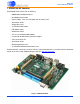
EDB9315A Technical Reference Manual 1. EDB9315A Kit Contents Each EDB9315A kit comes with the following: • EDB9315A Development Board • Null Modem Serial Cable • Power Supply: +12V, 5A, 110V/220V with AC Power Cord • Quick Start Guide • Registration Card • (2) IDC10-to-DB9 Cables • IDE Ribbon Cable • HDD Power Cable • 3.5"-to-2.
EDB9315A Technical Reference Manual 2. Introducing the EDB9315A Engineering Development Board This document will describe the features and basic operation of the EDB9315A board developed by Cirrus Logic. Detailed information regarding the operation and programming of the EP9315 device are covered by the EP9315 datasheet and User's Guide on the Cirrus Logic web site. The EDB9315A is a convenient and easy-to-operate evaluation platform.
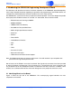
EDB9315A Technical Reference Manual L M N O P Q R K AA S J I E D A C B T H W U Z G F V Y X Figure 2. EDB9315A Top View N. USB Device Connector A. EP9315 processor O. Ethernet Connector B. Processor Status LEDs - one Red and one Green P. Dual, Stacked USB Host Connector C. USB 2.0 High-speed Device IC (ISP1581) Q. Audio Out Connector D. SDRAM - 2 16-bit devices R. Audio In Connector E. Memory Bus Expansion Connector S. Peripheral Bus Expansion Connector F. Main Power Switch, S1 T.
EDB9315A Technical Reference Manual 3. Getting Started 3.1 Before you Begin... The developer will find it useful to have some additional hardware not provided in the EDB9315A kit. Items such as a USB mouse, USB keyboard, VGA monitor and cable, and a set of powered speakers can make using the EDB9315A and the software installed on the board more enjoyable. Caution: Make sure you are in a static-free environment and are following proper procedures for handling ESD-sensitive electronic equipment. 3.
EDB9315A Technical Reference Manual the Qt/Opie desktop on the VGA monitor, depending which OS you have programmed into the board. The EDB9315A comes with WinCE 5.0 installed. NOTE: The WinCE 5.0 binary is not provided on the support web site. If you erase the image on the board, you will have to download the BSP provided by Cirrus Logic and compile it using Platform Builder. Due to changes in distribution policy, the Microsoft trial CD/DVD that was formerly included in the kit is no longer available.
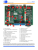
EDB9315A Technical Reference Manual 4. EDB9315A Circuit Description This chapter makes reference to the schematics in Appendix A and discusses the main circuit functionality of each schematic page. A detailed block diagram of the EDB9315A Engineering Development Board is shown below. JTAG 20 pin Memory Expansion 120 pin SDRAM 64 MByte 32-bit USB2. 0 Device ( High Speed) Flash 16 MByte 16-bit Audio In Audio Out RTC battery backed IDE 40 pin VGA DB15 CIR EP9315 POWER Vin = +12V Vout=1.8 , 3.3 , 5.
EDB9315A Technical Reference Manual 4.1 Circuit Operation The major circuit operation for each page of the schematic will be discussed. Note: Refer to http://arm.cirrus.com for the latest board schematics. Look under the download link at the top of the page. Page 1 Block diagram and revision history. Page 2 There are two main clock inputs to the EP9315 device. One is the 14.7456 MHz crystal oscillator and the other is the 32.768 kHz real time clock (RTC). The 14.
EDB9315A Technical Reference Manual Page 5 This is the power section for the EP9315 device. The ADC and PLL supplies are filtered. There is no reason to filter the 3.3 and the 1.8V power rails. Page 6 The SDRAM interface is comprised of two 16-bit SDRAM devices to form a 32-bit SDRAM bus. The SDRAM is connected to /SDCS0 and is located at physical memory address 0xC000_0000. Single 32bit SDRAM devices may be used as well. The Flash interface is made from a single 16-bit device.
EDB9315A Technical Reference Manual Page 9 The two connectors provide a daughter card interface for making custom circuits. J4 is the Memory Expansion connector and J5 is the Peripheral Expansion connector. The entire memory bus is connected to J5. It is recommended that the bus signals be buffered if adding additional memory. However if a CPLD or FPGA is attached there is no reason to buffer. Use proper engineering practices when using the high-speed memory bus with daughter cards.
EDB9315A Technical Reference Manual Page 14 Power and reset circuits are shown on this page. Most of the changes made to this revision of the EDB9315A board were made in this section. The most important change made is that the board is now powered from a +12V power supply instead of the former +5V supply. The board has two connectors for input power. J10 is the standard power connector and is where the power supply provided in the kit attaches.
EDB9315A Technical Reference Manual 5. Software 5.1 Overview The software programmed into the Flash on the EDB9315A development board is WinCE® 5.0. Linux® 2.6.8.1, from Cirrus Logic, running Qt/Opie is also available for the EDB9315A board The WinCE 5.0 image programmed into Flash by the factory is not available from Cirrus Logic directly. This image can not be provided to users due to distribution and royalty reasons. If the developer decides to overwrite the factory WinCE 5.
EDB9315A Technical Reference Manual 6. Developer’s User Forum Many references have been made to the Cirrus Logic Developers User's Forum in this document. The Cirrus Logic Developers User's Forum is a company-sponsored site and moderated by Cirrus Logic employees. However, it is not the technical help line for the Cirrus Logic ARM® product line. It is intended to be a place where developers can share ideas and ask questions from others.
EDB9315A Technical Reference Manual 7. Other Useful Information Web Sites • Cirrus Logic main web site: www.cirrus.com • Developer's Web Site: arm.cirrus.com • Registration Web Site: www.cirrus.com/boardreg Processor Information The following information is located on the www.cirrus.com web site. • EP9315 Datasheet • EP9315 User's Guide • EP9315 Errata Application Notes The following information is located on the www.cirrus.com web site.
EDB9315A Technical Reference Manual Appendix A. Schematics The schematics for the EDB9315A Development Board are located on the Cirrus Logic Developer’s Forum website ( arm.cirrus.com ). The schematics are provided in Adobe’s portable document format (PDF) and PADS™ format. OrCAD™ versions of the schematics are not available. 18 ©Copyright 2006 Cirrus Logic, Inc.
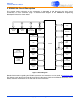
Figure 4. Schematic Page 1 - Block Diagram EDB9315A Technical Reference Manual DS638DB3 ©Copyright 2006 Cirrus Logic, Inc.
Figure 5. Schematic Page 2 - Processor & Memory EDB9315A Technical Reference Manual 20 ©Copyright 2006 Cirrus Logic, Inc.
Figure 6. Schematic Page 3 - Peripherals EDB9315A Technical Reference Manual DS638DB3 ©Copyright 2006 Cirrus Logic, Inc.
Figure 7. Schematic Page 4 - UARTs & USB EDB9315A Technical Reference Manual 22 ©Copyright 2006 Cirrus Logic, Inc.
Figure 8. Schematic Page 5 - µP Power EDB9315A Technical Reference Manual DS638DB3 ©Copyright 2006 Cirrus Logic, Inc.
Figure 9. Schematic Page 6 - SDRAM & Flash EDB9315A Technical Reference Manual 24 ©Copyright 2006 Cirrus Logic, Inc.
Figure 10. Schematic Page 7 - JTAG & CFG EDB9315A Technical Reference Manual DS638DB3 ©Copyright 2006 Cirrus Logic, Inc.
Figure 11. Schematic Page 8 - Ethernet EDB9315A Technical Reference Manual 26 ©Copyright 2006 Cirrus Logic, Inc.
Figure 12. Schematic Page 9 - Expansion Connector EDB9315A Technical Reference Manual DS638DB3 ©Copyright 2006 Cirrus Logic, Inc.
Figure 13. Schematic Page 10 - IDE EDB9315A Technical Reference Manual 28 ©Copyright 2006 Cirrus Logic, Inc.
Figure 14. Schematic Page 11 - VGA & LCD EDB9315A Technical Reference Manual DS638DB3 ©Copyright 2006 Cirrus Logic, Inc.
Figure 15. Schematic Page 12 - USB2.0 Slave EDB9315A Technical Reference Manual 30 ©Copyright 2006 Cirrus Logic, Inc.
Figure 16. Schematic Page 13 - Audio EDB9315A Technical Reference Manual DS638DB3 ©Copyright 2006 Cirrus Logic, Inc.
Figure 17. Schematic Page 14 - Power Supply EDB9315A Technical Reference Manual 32 ©Copyright 2006 Cirrus Logic, Inc.
EDB9315A Technical Reference Manual Appendix B. Programming Linux Images into Flash from a Windows® PC For those people who want to program Linux images onto the board but do not have a Linux PC. Materials and Equipment Needed A. +12V, 5 amp power supply, provided with kit B. Computer • Must be running Windows® 2000 or Windows® XP with SP2 installed on a Pentium® III or better with at least 256M RAM. • Must have at least one (1) serial port with DB9 connector.
EDB9315A Technical Reference Manual Downloading Files 1. Make a directory called "TFTPROOT" on C:\ 2. Use a computer that has an Internet connection and download the files specified in "D. Software" to the directory made in step 1. 3. Disconnect the Ethernet cable if using Wired Ethernet. Plug in the Ethernet cross-over cable into the computer's Ethernet port. Windows PC Ethernet Setup 1. Go to Control Panel, click on Network Connections.
EDB9315A Technical Reference Manual TFTP Server Setup (Setup may vary depending on TFTP server used) 1. Install the TFTP Server program on the Windows PC and select the default configuration. 2. You may have to disable the firewall if using Windows XP. 3. Once the program is installed, run the TFTP Server program. 4. Configure the TFTP Root directory to point to C:\TFTPROOT. 5. Select the Security Tab and make sure the Client access is Transmit and Receive files. See the pictures below.
EDB9315A Technical Reference Manual 6. Verify that the Auto-Close setting is set to "Never". 7. When complete, click the OK button. You should see a screen like the picture below. Note that the directory is located in the status bar at the bottom left. Additionally, the IP address the TFTP Server is "listening" to is located in the lower right. Note: 36 Note: You may get an IP address of 127.0.0.1 because the EDB9315A board does not have the boot loader code programmed yet. This is ok.
EDB9315A Technical Reference Manual HyperTerminal Setup Run the HyperTerminal program and configure to use COM1 and to run at 57600 baud, 8 data bits, no parity, one (1) stop bit (8-N-1) and NO hardware control flow. It should look like the picture below when complete. Note you have to "Disconnect" in order to make configuration changes. Click "Call" once the configuration is complete. DS638DB3 ©Copyright 2006 Cirrus Logic, Inc.
EDB9315A Technical Reference Manual Board Programming Setup 1. At this point, the RJ45 Ethernet port on the Windows PC is configured, HyperTerminal is running, the TFTP server is running, the Cirrus Logic software has been downloaded to the C:\TFTPROOT directory and the board is powered up. 2. Connect one end of the Null Modem cable to J2. 3. Connect the other end of the Null Modem cable to the COM1 port on the Windows 2000/XP computer. 4. Connect the other end of the Ethernet cross-over cable to J3.
EDB9315A Technical Reference Manual download.exe Downloading the Code download.exe Erasing then Programming the Flash Memory download.exe Successfully Programming redboot.bin DS638DB3 ©Copyright 2006 Cirrus Logic, Inc.
EDB9315A Technical Reference Manual 3. Redboot.bin has been programmed into Flash memory. Go to HyperTerminal and re-establish serial communication to the board by pressing the Call button. 4. Press and release pushbutton S3, /POR. The board will reboot and eventually display information in the HyperTerminal window. Note: The initial error about configuration checksum error is expected for a brand new board or a board where the Flash device has been completely erased.
EDB9315A Technical Reference Manual 7. The MAC address label on the top of the board has a hexadecimal number on it. It has the following format: AB1234567890. When programming the MAC address, use the following format: 0xAB:0x12:0x34:0x56:0x78:0x90. This is an example MAC address. 8. Remember, assign a unique MAC address to each board. 9. Press and release pushbutton S3 "/POR" for the changes to take effect. You should see the following. Note: DS638DB3 It will say "No image 'image_name' found".
EDB9315A Technical Reference Manual 10. Execute the following command: load -v -r -b 0xa00000 ramdisk.gz 11. You will see a spinning character in the bottom left hand side of the window. Wait until the RedBoot> prompt returns. 12. Next type: fis create -b 0xa00000 -l 0xa00000 ramdisk 13. This command will program the ramdisk.gz file into a Flash partition called ramdisk. Wait until the RedBoot> prompt returns. 14. Execute the following command: load -v -r -b 0x80000 zImage 15.
EDB9315A Technical Reference Manual Once the board has been programmed, reset the board and wait for it to boot up. You will see the following (or similar) screen on the display.. DS638DB3 ©Copyright 2006 Cirrus Logic, Inc.
EDB9315A Technical Reference Manual Revision History Revision Date Changes DB1 DEC 2005 First release. DB2 AUG 2006 Updated for Rev C PCB. Reference designator S2 changed to S1 (power switch). Rev C board is identified by the revision level printed next to the serial number on the backside of the PCB under the UART0 connector, J2. DB3 AUG 2006 Corrected schematic page numbering - schematic page 9.