
User guide


DS206DB2 3
CDB8952
Crystal LAN™ 10Base-T and 100Base-X Transceiver
CIRRUS LOGIC ADVANCED PRODUCT DATABOOK
NOTE: Physical address 00000 is a special broadcast
address. All devices will respond to this address
in addition to the one selected using S3. Setting
S3 to 00000 will cause the CS8952 to set the
ISOLATE bit in the Basic Mode Control Regis-
ter, isolating itself from all MII signals except
MDC and MDIO. It will remain isolated until this
bit is cleared.
Care should be taken when reading from phys-
ical address 00000 when multiple devices
reside on the same MII.
HDR1 - MII Drive Select. When this header is left
open, the CS8952 MII drivers will conform to the
IEEE 802.3u specification. When a shorting cap is
installed, the CS8952 MII drivers will be reduced
to 4mA.
The CS8952 checks the status of HDR1 only dur-
ing power-on or reset. A reset or power cycle is re-
quired before any changes in this jumper setting
will take effect.
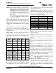
HDR4, HDR5 - Auto-Negotiation Select 0 and 1.
These headers are used to select the forced or ad-
vertised auto-negotiation modes as indicated in Ta-
ble 4.
The CS8952 checks the status of HDR4 and HDR5
only during power-on or reset. A reset or power cy-
cle is required before any changes in these jumper
settings will take effect.
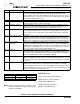
HDR6, HDR7 - Transmit Slew Rate Select 0 and 1.
These headers are used to select the rise and fall
times of the 100BASE-TX transmitter output
waveform as indicated in Table 5.
HDR15 - Table 6 describes the effect of shorting
the listed pin pairs.
HDR34 - Test 0. This header is for factory test pur-
poses only, and should be left open for normal op-
eration.
HDR35 - Test 1. This header is for factory test pur-
poses only, and should be left open for normal op-
eration.
HDR42 - TX_CLK Source Select. This header, in
conjunction with HDR43, is used to select the
TX_CLK source. When pins 1 and 2 are selected,
TX_CLK is supplied from the CS8952 CLK25 out-
put. When pins 2 and 3 are shorted, TX_CLK is
supplied externally from J1. When no shorting cap
is installed, HDR43 must be configured so that
TX_CLK is an output from the CS8952.
NOTE: No shorting cap should be installed on this
header when TX_CLK is configured as an out-
put (see HDR43).
HDR43 - TX_CLK Mode Select. (Table 7)
The CS8952 checks the status of HDR43 only dur-
ing power-on or reset. A reset or power cycle is re-
quired before any changes in this jumper setting
will take effect.
HDR5
(AN1)
HDR4
(AN0) Speed
Forced/
Auto
Full/Hal
fDuplex
pins 2-3
shorted
open 10 Forced Half
pins 1-2
shorted
open 10 Forced Full
open pins 2-3
shorted
100 Forced Half
open pins 1-2
shorted
100 Forced Full
open open 100/10 Auto Full/Half
pins 2-3
shorted
pins 2-3
shorted
10 Auto Half
pins 2-3
shorted
pins 1-2
shorted
10 Auto Full
pins 1-2
shorted
pins 2-3
shorted
100 Auto Half
pins 1-2
shorted
pins 1-2
shorted
100 Auto Full
Table 4. Auto-Negotiation Select
HDR7
(TXSLEW1)
HDR6
(TXSLEW0)
Rise/Fall
Time
pins 2-3 shorted pins 2-3 shorted 0.5 ns
open pins 2-3 shorted 1.0 ns
pins 1-2 shorted pins 2-3 shorted 1.5 ns
pins 2-3 shorted open 2.0 ns
open open 2.5 ns
pins 1-2 shorted open 3.0 ns
pins 2-3 shorted pins 1-2 shorted 3.5 ns
open pins 1-2 shorted 4.0 ns
pins 1-2 shorted pins 1-2 shorted 4.5 ns
Table 5. Transmit Slew Rate