
User guide


2 DS206DB2
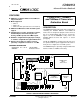
CDB8952
Crystal LAN™ 10Base-T and 100Base-X Transceiver
CIRRUS LOGIC ADVANCED PRODUCT DATABOOK
INTRODUCTION
This manual provides information specifically on
the CDB8952 Evaluation board and generally on
any design incorporating the CS8952 Crystal-
LAN
TM
10Base-T and 100Base-X Transceiver.
The reader should have a general knowledge of
hardware design and Ethernet operation.
Background Information
• IEEE Std 802.3u-1995 (ISO/IEC 8802.3:1996)
CSMA/CD Access Method and Physical Layer
Specifications
• IEEE Std 802.3u-1995 Supplement Clause 28
(Auto-
Negotiation)
• CS8952 CrystalLAN
TM
10Base-T and
100Base-X Transceiver Datasheet
Evaluation Kit Contents
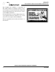
The CDB8952 Evaluation Board Kit includes the
following:
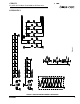
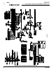
BOARD CONFIGURATION
I/O Connectors
J1 - External TX_CLK. This connector may be
used to supply TX_CLK when HDR42 and HDR43
are set appropriately.
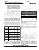
J2 - RJ45, Twisted-pair Media (Table 2).
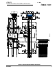
J5 - MII Power. When the board is connected to a
system that does not supply power through the MII
connector, +5 V or +3.3 V must be supplied here.
J6 - CS8952 Core Power. +5 V must be supplied
here from either J5 (if +5 V is supplied through the
MII connector) or an external power supply.
J13 - MII Connector (Table 3).
Configuration Jumpers and Switches
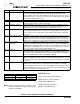
S1 - Board Reset. Depressing this push-button
switch will force the CS8952 into a reset state.
S2 - Test 1 (not populated). This switch is used to
select a factory test mode, and should not be
pressed during normal operation.
S3 - Physical Address Select. This 5-position
switch is used to select the physical address to
which the CS8952 will respond. “Open” or “Off”
will set the corresponding physical address bit to
ZERO, while “Closed” or “On” will set it to ONE.
The CS8952 checks the positions of this switch
only during power-up or reset. If any switch posi-
tion is changed, a reset or power cycle is required
before the new settings will take effect.
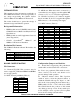
Quantity Item
1 CDB8952 Evaluation Board
1 CS8952 Datasheet
1 CDB8952 Reference Manual
1 CDB8952 Kit Packing List
Table 1. Evaluation Kit Contents
Pin Function
1TD+
2TD-
3RD+
4-
5-
6 RD-
7-
8-
Table2.Twisted-pairMedia
Pin Function Pin Function
1 MII Power 21 MII Power
2 MDIO 22 Ground
3 MDC 23 Ground
4 RXD3 24 Ground
5 RXD2 25 Ground
6 RXD1 26 Ground
7 RXD0 27 Ground
8 RX_DV 28 Ground
9 RX_CLK 29 Ground
10 RX_ER/RXD4 30 Ground
11 TX_ER/TXD4 31 Ground
12 TX_CLK 32 Ground
13 TX_EN 33 Ground
14 TXD0 34 Ground
15 TXD1 35 Ground
16 TXD2 36 Ground
17 TXD3 37 Ground
18 COL 38 Ground
19 CRS 39 Ground
20 MII Power 40 MII Power
Table 3. MII Connector