
Instruction Manual


64 DS271F5
CS8900A
Crystal LAN™ Ethernet Controller
CIRRUS LOGIC PRODUCT DATASHEET
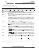
4.4.18 Register 15: Self Control
(SelfCTL, Read/Write, Address: PacketPage base + 0114h)
SelfCTL controls the operation of the LED outputs and the lower-power modes.
010101 These bits provide an internal address used by the CS8900A to identify this as the Chip Self
Control Register.
RESET When set, a chip-wide reset is initiated immediately. RESET is an Act-Once bit. This bit is
cleared as a result of the reset.
SWSuspend When set, the CS8900A enters the software initiated Suspend mode. Upon entering this mode,
there is a partial reset. All registers and circuits are reset except for the ISA I/O Base Address
Register and the SelfCTL Register. There is no transmit nor receive activity in this mode. To
come out of software Suspend, the host issues an I/O Write within the CS8900A's assigned I/O
space (see Section 3.7 on page 27 for a complete description of the CS8900A's low-power
modes).
HWSleepE When set, the SLEEP
input pin is enabled. If SLEEP is high, the CS8900A is "awake", or oper-
ative (unless in SWSuspend mode, as shown above). If SLEEP
is low, the CS8900A enters ei-
ther the Hardware Standby or Hardware Suspend mode. When clear, the CS8900A ignores the
SLEEP
input pin (see Section 3.7 on page 27 for a complete description of the CS8900A's low-
power modes).
HWStandbyE If HWSleepE is set and the SLEEP
input pin is low, then when HWStandbyE is set, the
CS8900A enters the Hardware Standby mode. When clear, the CS8900A enters the Hardware
Suspend mode (see Section 3.7 on page 27 for a complete description of the CS8900A's low-
power modes).
HC0E The LINKLED
or HC0 output pin is selected with this control bit. When HC0E is clear, the output
pin is LINKLED
. When HC0E is set, the output pin is HC0 and the HCB0 bit (Bit E) controls the
pin.
HC1E The BSTATUS
or HC1 output pin is selected with this control bit. When HC1E is clear, the out-
put pin is BSTATUS
and indicates receiver ISA Bus activity. When HC1E is set, the output pin
is HC1
and the HCB1 bit (Bit F) controls the pin.
HCB0 When HC0E (Bit C) is set, this bit controls the HC0
pin. If HCB0 is set, HC0 is low. If HCB0 is
clear, HC0
is high. HC0 may drive an LED or a logic gate. When HC0E (Bit C) is clear, this con-
trol bit is ignored.
HCB1 When HC1E (Bit D) is set, this bit controls the HC1
pin. If HCB1 is set, HC1 is low. If HCB1 is
clear, HC1
is high. HC1 may drive an LED or a logic gate. When HC1E (Bit D) is clear, this con-
trol bit is ignored.
After reset, if no EEPROM is found by the CS8900A, then the register has the following initial state. If an EEPROM
is found, then the register's initial value may be set by the EEPROM. See Section 3.3 on page 19.
Reset value is: 0000 0000 0001 0101
76543210
RESET 010101
FEDCBA9 8
HCB1 HCB0 HC1E HC0E HW Standby HWSleepE SW Suspend