
Instruction Manual

22 DS271F5
CS8900A
Crystal LAN™ Ethernet Controller
CIRRUS LOGIC PRODUCT DATASHEET
the EEPROM). Address space 80h to AFh is
reserved.
3.4.3.1 Reset Configuration Block Structure
The Reset Configuration Block is a block of
contiguous 16-bit words starting at EEPROM
address 00h. It can be divided into three logi-
cal sections: a header, one or more groups of
configuration data words, and a checksum val-
ue. All of the words in the Reset Configuration
Block are read sequentially by the CS8900A
after each reset, starting with the header and
ending with the checksum. Each group of con-
figuration data is used to program a Packet-
Page register (or set of PacketPage registers
in some cases) with an initial non-default val-
ue.
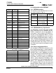
3.4.3.2 Reset Configuration Block Header
The header (first word of the block located at
EEPROM address 00h) specifies the type of
EEPROM used, whether or not a Reset Con-
figuration block is present, and if so, how many
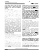
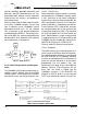
Word Address Value Description
FIRST WORD in DATA BLOCK
00h A120h Configuration Block Header.
The high byte, A1h, indicates a ‘C46 EEPROM is attached. The Link Byte,
20h, indicates the number of bytes to be used in this block of configuration
data.
FIRST GROUP of WORDS
01h 2020h Group Header for first group of words.
Three words to be loaded, beginning at 0020h in PacketPage memory.
02h 0300h I/O Base Address
03h 0003h Interrupt Number
04h 0001h DMA Channel Number
SECOND GROUP of WORDS
05h 502Ch Group Header for second group of words.
Six words to be loaded, beginning at 002Ch in PacketPage memory.
06h E000h Memory Base Address - low word
07h 000Fh Memory Base Address - high word
08h 0000h Boot PROM Base Address - low word
09h 000Dh Boot PROM Base Address - high word
0Ah C000h Boot PROM Address Mask - low word
0Bh 000Fh Boot PROM Address Mask - high word
THIRD GROUP of WORDS
0Ch 2158h Group Header for third group of words.
Three words to be loaded, beginning at 0158 in PacketPage memory.
0Dh 0010h Individual Address - Octet 0 and 1
0Eh 0000h Individual Address - Octet 2 and 3
0Fh 0000h Individual Address - Octet 4 and 5
CHECKSUM Value
10h 2800h The high byte, 28h, is the Checksum Value. In this example, the checksum
includes word addresses 00h through 0Fh. The hexadecimal sum of the
bytes is D8h, resulting in a 2’s complement of 28h. The low byte, 00h, pro-
vides a pad to the word boundary.
* FFFFh is a special code indicating that there are no more words in the EEPROM.
Table 7. EEPROM Configuration Block Example