
Instruction Manual

DS271F5 21
CS8900A
Crystal LAN™ Ethernet Controller
CIRRUS LOGIC PRODUCT DATASHEET
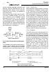
3.4 Configurations with EEPROM
3.4.1 EEPROM Interface
The interface to the EEPROM consists of the
four signals shown in Table 6.
3.4.2 EEPROM Memory Organization
If an EEPROM is used to store initial configu-
ration information for the CS8900A, the EE-
PROM is organized in one or more blocks of
16-bit words. The first block in EEPROM, re-
ferred to as the Configuration Block, is used to
configure the CS8900A after reset. An exam-
ple of a typical Configuration Block is shown in
Table 7. Additional blocks containing user data
may be stored in the EEPROM. However, the
Configuration Block must always start at ad-
dress 00h and be stored in contiguous memo-
ry locations.
3.4.3 Reset Configuration Block
The first block in EEPROM, referred to as the
Reset Configuration Block, is used to automat-
ically program the CS8900A with an initial con-
figuration after a reset. Additional user data
may also be stored in the EEPROM if space is
available. The additional data are stored as
16-bit words and can occupy any EEPROM
address space beginning immediately after
the end of the Reset Configuration Block up to
address 7Fh, depending on EEPROM size.
This additional data can only be accessed
through software control (refer to Section 3.5
on page 25 for more information on accessing
PacketPage
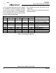
Address
Register
Contents
Register Descriptions
0020h 0300h I/O Base Address*
0022h XXXX XXXX
XXXX X100
Interrupt Number
0024h XXXX XXXX
XXXX XX11
DMA Channel
0026h 0000h DMA Start of Frame
Offset
0028h X000h DMA Frame Count
002Ah 0000h DMA Byte Count
002Ch XXX0 0000h Memory Base Address
0030h XXX0 0000h Boot PROM Base
Address
0034h XXX0 0000h Boot PROM Address
Mask
0102h 0003h Register 3 - RxCFG
0104h 0005h Register 5 - RxCTL
0106h 0007h Register 7 - TxCFG
0108h 0009h Register 9 - TxCMD
010Ah 000Bh Register B - BufCFG
010Ch Undefined Reserved
010Eh Undefined Reserved
0110h Undefined Reserved
0112h 00013h Register 13 - LineCTL
0114h 0015h Register 15 - SelfCTL
0116h 0017h Register 17 - BusCTL
0118h 0019h Register 19 - TestCTL
* I/O base address is unaffected by Software Suspend mode.
Table 4. Default Configuration
EEPROM Type Size (16-bit words)
‘C46 (non-sequential) 64
‘CS46 (sequential) 64
‘C56 (non-sequential) 128
‘CS56 (sequential) 128
‘C66 (non-sequential) 256
‘CS66 (sequential) 256
Table 5. Supported EEPROM Types
CS8900A Pin
(Pin #) CS8900A Function
EEPROM
Pin
EECS (Pin 3) EEPROM Chip Select Chip Select
EESK (PIN 4) 1 MHz EEPROM
Serial Clock output
Clock
EEDO (Pin 5) EEPROM Data Out
(data to EEPROM)
Data In
EEDI (Pin 6) EEPROM Data in
(data from EEPROM)
Data Out
Table 6. EEPROM Interface