
Instruction Manual


DS271F5 109
CS8900A
Crystal LAN™ Ethernet Controller
CIRRUS LOGIC PRODUCT DATASHEET
The input pins not included in this test are:
After the Input Cycle is complete, one more cy-
cle of AEN returns all digital output pins and bi-
directional pins to a high-impedance state.
6.2.3 Continuity Cycle
The combination of a complete Output Cycle,
a complete Input Cycle, and an additional AEN
cycle is called a Continuity Cycle. Each Conti-
nuity Cycle lasts for 85 AEN clock cycles. The
first Continuity Cycle can be followed by addi-
tional Continuity Cycles by keeping TEST low
and continuing to cycle AEN. When TEST is
driven high, the CS8900A exits Boundary
Scan mode and AEN is again used as the ISA-
bus Address Enable.
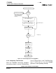
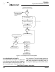
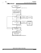
Figure 32 shows a complete Boundary Scan
Continuity Cycle.
Figure 33 shows Boundary Scan timing.
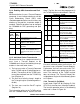
DMACK1 14 IOR 61
DMACK0 16 IOW 62
SD08-SD15 27-24, 21-18 SD0 - SD7 65-68, 71-74
MEMW 28 RESET 75
MEMR 29 SLEEP 77
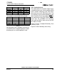
Pin Name Pin # Pin Name Pin #
AEN 63 Cl- 82
TEST 76 RXD+ 91
Dl+ 79 RXD- 92
Dl- 80 XTAL1 97
Cl+ 81
Table 42.
Pin Name Pin # Pin Name Pin #
Table 41. (continued)