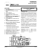
CS8900A Product Data Sheet FEATURES Crystal LAN™ Ethernet Controller Single-Chip IEEE 802.
CS8900A Crystal LAN™ Ethernet Controller TABLE OF CONTENTS 1.0 INTRODUCTION ......................................................................................................................8 1.1 General Description ...........................................................................................................8 1.1.1 Direct ISA-Bus Interface .......................................................................................8 1.1.2 Integrated Memory .......................................
CS8900A Crystal LAN™ Ethernet Controller 3.4.7.1 Determining EEPROM Size .................................................................24 3.4.7.2 Loading Configuration Data .................................................................24 3.4.8 EEPROM Read-out Completion ......................................................................... 24 3.5 Programming the EEPROM ............................................................................................ 25 3.5.1 EEPROM Commands .............
CS8900A Crystal LAN™ Ethernet Controller 3.10.4 Interface Selection ............................................................................................36 3.10.4.1 10BASE-T Only .................................................................................36 3.10.4.2 AUI Only ............................................................................................36 3.10.4.3 Auto-Select ........................................................................................36 3.
CS8900A Crystal LAN™ Ethernet Controller 4.10.2 TxCMD Port ...................................................................................................... 75 4.10.3 TxLength Port ................................................................................................... 76 4.10.4 Interrupt Status Queue Port ............................................................................. 76 4.10.5 PacketPage Pointer Port ............................................................................
CS8900A Crystal LAN™ Ethernet Controller 5.4.1 Overview .............................................................................................................94 5.4.2 Configuring the CS8900A for Auto-Switch DMA .................................................94 5.4.3 Auto-Switch DMA Operation ...............................................................................94 5.4.4 DMA Channel Speed vs. Missed Frames ...........................................................95 5.4.5 Exit From DMA ....
CS8900A Crystal LAN™ Ethernet Controller Table 1. Revision History Release PP1 PP2 PP3 PP4 Date NOV 1997 DEC 1998 MAR 1999 APR 2001 F1 JAN 2004 F2 F3 F4 F5 JUL 2004 SEP2004 AUG 2007 SEP 2010 Changes Preliminary Release, revision 1 Preliminary Release, revision 2 Preliminary Release, revision 3 Preliminary Release, revision 4 Page 13: INTRQ[0:2] changed to INTRQ[0..
CS8900A Crystal LAN™ Ethernet Controller 1.0 INTRODUCTION 1.1 General Description The CS8900A is a true single-chip, full-duplex, Ethernet solution, incorporating all of the analog and digital circuitry needed for a complete Ethernet circuit. Major functional blocks include: a direct ISA-bus interface; an 802.3 MAC engine; integrated buffer memory; a serial EEPROM interface; and a complete analog front end with both 10BASE-T and AUI. 1.1.
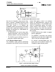
CS8900A Crystal LAN™ Ethernet Controller (2.0 sq. in.) EEPROM 20 MHz XTAL I S A RJ-45 CS8900A 10BASE-T Figure 1. Complete Ethernet Motherboard Solution high level of integration allow System Engineers to design a complete Ethernet circuit that occupies as little as 1.5 square inches of PCB area (Figure 1). In addition, the CS8900A’s power-saving features and CMOS design make it a perfect fit for power-sensitive portable and desktop PCs.
CS8900A Crystal LAN™ Ethernet Controller • On-chip LED ports can be used for either optional LEDs, or as programmable outputs. 1.3 Key Features and Benefits 1.3.1 Very Low Cost The CS8900A is designed to provide the lowest-cost Ethernet solution available for embedded applications, portable motherboards, nonISA bus systems and adapter cards. Cost-saving features include: • Integrated RAM eliminates the need for expensive external memory chips.
CS8900A Crystal LAN™ Ethernet Controller 20 MHz EEPROM 93C46 CS 1 3 5V 4.
CS8900A Crystal LAN™ Ethernet Controller 100 99 98 97 96 95 94 93 92 91 90 89 88 87 86 85 84 83 82 81 80 79 78 77 76 LANLED LINKLED or HC0 XTAL2 XTAL1 AVSS4 AVDD3 AVSS3 RES RXD RXD + AVDD1 AVSS1 TXD TXD + AVSS2 AVDD2 DODO+ CICI+ DIDI+ BSTATUS or HC1 SLEEP TEST 2.
CS8900A Crystal LAN™ Ethernet Controller ISA Bus Interface SA[0:19] - System Address Bus, Input PINS 37-48, 50-54, 58-60. Lower 20 bits of the 24-bit System Address Bus used to decode accesses to CS8900A I/O and Memory space, and attached Boot PROM. SA0-SA15 are used for I/O Read and Write operations. SA0-SA19 are used in conjunction with external decode logic for Memory Read and Write operations. SD[0:15] - System Data Bus, Bi-Directional with 3-State Output PINS 65-68, 71-74, 2724, 21-18.
CS8900A Crystal LAN™ Ethernet Controller IOW - I/O Write, Input PIN 62. When IOW is low and a valid address is detected, the CS8900A writes the data on the System Data Bus into the selected 16-bit I/O register. IOW is ignored if REFRESH is low. IOCS16 - I/O Chip Select 16-bit, Open Drain Output PIN 33. Open-drain, active-low output generated by the CS8900A when it recognizes an address on the ISA bus that corresponds to its assigned I/O space. 3-Stated when not active.
CS8900A Crystal LAN™ Ethernet Controller EECS - EEPROM Chip Select, PIN 3. Active-high output used to select the EEPROM. EEDataIn - EEPROM Data In, Input Internal Weak Pullup PIN 6. Serial input used to receive data from the EEPROM. Connects to the DO pin on the EEPROM. EEDataIn is also used to sense the presence of the EEPROM. ELCS - External Logic Chip Select, Internal Weak Pullup PIN 2. Bi-directional signal used to configure external Latchable Address (LA) decode logic.
CS8900A Crystal LAN™ Ethernet Controller General Pins XTAL[1:2] - Crystal, Input/Output PINS 97 and 98. A 20 MHz crystal should be connected across these pins. If a crystal is not used, a 20 MHz signal should be connected to XTAL1 and XTAL2 should be left open. (See Section 7.3 on page 112 and Section 7.7 on page 122.) SLEEP - Hardware Sleep, Input Internal Weak Pullup PIN 77. Active-low input used to enable the two hardware sleep modes: Hardware Suspend and Hardware Standby. (See Section 3.7 on page 27.
CS8900A Crystal LAN™ Ethernet Controller 3.0 FUNCTIONAL DESCRIPTION 3.1 Overview During normal operation, the CS8900A performs two basic functions: Ethernet packet transmission and reception. Before transmission or reception is possible, the CS8900A must be configured. 3.1.1 Configuration The CS8900A must be configured for packet transmission and reception at power-up or reset.
CS8900A Crystal LAN™ Ethernet Controller as Memory space operations, I/O space operations, or as DMA operations using host DMA. Also, the CS8900A provides the capability to switch between Memory or I/O operation and DMA operation by using Auto-Switch DMA and StreamTransfer. The Section 5.2 on page 78 through Section 5.5 on page 96 provide a detailed description of packet reception. 3.2 ISA Bus Interface The CS8900A provides a direct interface to ISA buses running at clock rates from 8 to 11 MHz.
CS8900A Crystal LAN™ Ethernet Controller memory. The CS8900A has three pairs of DMA pins that can be connected directly to the three 16-bit DMA channels of the ISA bus. Only one DMA channel is used at a time. It is selected during initialization by writing the number of the desired channel (0, 1 or 2) into PacketPage Memory base + 0024h. Unused DMA pins are placed in a high-impedance state. The selected DMA request pin goes high when the CS8900A has received frames to transfer to the host memory via DMA.
CS8900A Crystal LAN™ Ethernet Controller 3.3.2 Allowing Time for Reset Operation After a reset, the CS8900A goes through a self configuration. This includes calibrating on-chip analog circuitry, and reading EEPROM for validity and configuration. Time required for the reset calibration is typically 10 ms. Software drivers should not access registers internal to the CS8900A during this time.
CS8900A Crystal LAN™ Ethernet Controller 3.4 Configurations with EEPROM PacketPage Address Register Contents Register Descriptions 0020h 0300h I/O Base Address* 0022h XXXX XXXX Interrupt Number XXXX X100 3.4.1 EEPROM Interface The interface to the EEPROM consists of the four signals shown in Table 6.
CS8900A Crystal LAN™ Ethernet Controller Word Address Value FIRST WORD in DATA BLOCK 00h A120h FIRST GROUP of WORDS 01h 2020h 02h 0300h 03h 0003h 04h 0001h SECOND GROUP of WORDS 05h 502Ch 06h E000h 07h 000Fh 08h 0000h 09h 000Dh 0Ah C000h 0Bh 000Fh THIRD GROUP of WORDS 0Ch 2158h 0Dh 0Eh 0Fh CHECKSUM Value 10h 0010h 0000h 0000h 2800h Description Configuration Block Header. The high byte, A1h, indicates a ‘C46 EEPROM is attached.
CS8900A Crystal LAN™ Ethernet Controller bytes of configuration data are stored in the Reset Configuration Block. 3.4.3.3 Determining the EEPROM Type The LSB of the high byte of the header indicates the type of EEPROM attached: sequential or non-sequential. An LSB of 0 (XXXXXXX0) indicates a sequential EEPROM. An LSB of 1 (XXXX-XXX1) indicates a non-sequential EEPROM. The CS8900A works equally well with either type of EEPROM.
CS8900A Crystal LAN™ Ethernet Controller Bits 8 through 0 of the Group Header specify a 9-bit PacketPage Address. This address defines the PacketPage register that will be loaded with the first word of configuration data from the group. Bits B though 9 of the Group Header are forced to 0, restricting the destination address range to the first 512 bytes of PacketPage memory. Figure 4 shows the format of the Group header. 3.4.
CS8900A Crystal LAN™ Ethernet Controller initialization is complete (configuration loaded from EEPROM or reset to default configuration) the INITD bit is set (Register 16, SelfST, bit 7). 3.5 Programming the EEPROM After initialization, the host can access the EEPROM through the CS8900A by writing one of seven commands to the EEPROM Command register (PacketPage base + 0040h). Figure 5 shows the format of the EEPROM Command register. 3.5.
CS8900A Crystal LAN™ Ethernet Controller (for a ’C56, ’CS56, ’C66 or ’CS66), are shifted out of the CS8900A, into the EEPROM. If the command is a Write, the data in the EEPROM Data register (PacketPage base + 0042h) follows. If the command is a Read, the data in the specified EEPROM location is written into the EEPROM Data register. If the command is an Erase or Erase-All, no data is transferred to or from the EEPROM Data register.
CS8900A Crystal LAN™ Ethernet Controller and the Address Mask is FC000h. This configuration describes a 16-Kbyte (128 Kbit) PROM mapped into host memory from D0000h to D3FFFh. 3.7 Low-Power Modes For power-sensitive applications, the CS8900A supports three low-power modes: Hardware Standby, Hardware Suspend, and Software Suspend. All three low-power modes are controlled through the SelfCTL register (Register 15). See also Section 4.4.4 on page 51.
CS8900A Crystal LAN™ Ethernet Controller 8). To exit SW Suspend, the host must write to the CS8900A’s assigned I/O space (the Write is only used to wake the CS8900A, the Write itself is ignored). Upon exit, the CS8900A performs a complete reset, and then goes through a normal initialization procedure. Any hardware reset takes the chip out of any sleep mode. Table 9 summarizes the operation of the three low-power modes.
CS8900A Crystal LAN™ Ethernet Controller 3.8 LED Outputs The CS8900A provides three output pins that can be used to control LEDs or external logic. 3.8.1 LANLED LANLED goes low whenever the CS8900A transmits or receives a frame, or when it detects a collision. LANLED remains low until there has been no activity for 6 ms (i.e. each transmission, reception, or collision produces a pulse lasting a minimum of 6 ms). 3.8.2 LINKLED or HC0 LINKLED or HC0 can be controlled by either the CS8900A or the host.
CS8900A Crystal LAN™ Ethernet Controller collision detection, preamble generation and detection, and CRC generation and test. Programmable MAC features include automatic retransmission on collision, and padding of transmitted frames. Figure 8 shows how the MAC engine interfaces to other CS8900A functions. On the host side, it interfaces to the CS8900A’s internal data/address/control bus. On the network side, it interfaces to the internal Manchester encoder/decoder (ENDEC).
CS8900A Crystal LAN™ Ethernet Controller tire packet has been received, the MAC validates the FCS. If an error is detected, the CRCerror bit (Register 4, RxEvent, Bit C) is set. 3.9.2.3 Enforcing Minimum Frame Size The MAC provides minimum frame size enforcement of both transmit and receive packets. When the TxPadDis bit (Register 9, TxCMD, Bit D) is clear, transmit frames will be padded with additional bits to ensure that the receiving station receives a legal frame (64 bytes, including CRC).
CS8900A Crystal LAN™ Ethernet Controller network collisions. The collision count is stored in bits B through E of the TxEvent register (Register 8). If the packet collides 16 times, transmission of that packet is terminated and the 16coll bit (Register 8, TxEvent, Bit F) is set. If the 16colliE bit (Register 7, TxCFG, Bit F) is set, the host will be interrupted on the 16th collision. A running count of transmit collisions is recorded in the TxCOL register. 3.9.3.
CS8900A Crystal LAN™ Ethernet Controller attempting transmission. The CS8900A supports two schemes for determining when to initiate transmission: Two-Part Deferral, and Simple Deferral. Selection of the deferral scheme is determined by the 2-partDefDis bit (Register 13, LineCTL, Bit D). If the 2-partDefDis bit is clear, the MAC uses a two-part deferral process defined in section 4.2.3.2.1 of the Ethernet standard (ISO/IEC 8802-3, 1993).
CS8900A Crystal LAN™ Ethernet Controller 3.9.5.4 Collision Resolution If a collision is detected while the CS8900A is transmitting, the MAC responds in one of three ways depending on whether it is a normal collision (within the first 512 bits of transmission) or a late collision (after the first 512 bits of transmission): 3.9.5.
CS8900A Crystal LAN™ Ethernet Controller transmission. The SQE Test is a 10 MHz signal lasting 5 to 15 bit times and starting within 0.6 to 1.6 µs after the end of transmission. During this period, the CS8900A ignores receive carrier activity (see SQE Error in this section for more information). bit times), and k is the smaller of n or 10, where n is the number of retransmission attempts. 3.9.5.9 Modified Backoff The Modified Backoff is described by the equation: 0 ≤ r ≤ 2k 3.
CS8900A Crystal LAN™ Ethernet Controller 40% and 60%. The specifications for the crystal are described in Section 7.7 on page 122. The encoded signal is routed to either the 10BASE-T transceiver or AUI, depending on configuration. 3.10.2 Carrier Detection The internal Carrier Detection circuit informs the MAC that valid receive data is present by asserting the internal Carrier Sense signal as soon it detects a valid bit pattern (1010b or 0101b for 10BASE-T, and 1b or 0b for AUI).
CS8900A Crystal LAN™ Ethernet Controller LinkOK (to MAC) 10BASE-T Transceiver Link Pulse Detector RX Squelch RXSQL RX ENDEC TX TX PreDistortion RX Comparator RX Filters TX Filters TX Drivers RXDRXD+ TXDTXD+ Filter Tuning Figure 13. 10BASE-T Transceiver 3.11.1 10BASE-T Filters The CS8900A’s 10BASE-T transceiver includes integrated low-pass transmit and receive filters, eliminating the need for external filters or a filter/transformer hybrid.
CS8900A Crystal LAN™ Ethernet Controller squelch threshold (either positive or negative, depending on polarity) is rejected. 3.11.3.2 Extended Range The CS8900A supports an Extended Range feature that reduces the 10BASE-T receive squelch threshold by approximately 6 dB. This allows the CS8900A to operate with 10BASET cables that are longer than 100 meters (100 meters is the maximum length specified by the Ethernet standard).
CS8900A Crystal LAN™ Ethernet Controller at least four frames in a row with negative polarity after the EOF, the receive pair is considered reversed. Any data received before the correction of the reversal is ignored. 3.11.6 Collision Detection If half-duplex operation is selected (Register 19, Bit E, FDX), the CS8900A detects a 10BASE-T collision whenever the receiver and transmitter are active simultaneously.
CS8900A Crystal LAN™ Ethernet Controller 3.13 External Clock Oscillator A 20-MHz quartz crystal or CMOS clock input is required by the CS8900A. If a CMOS clock input is used, it should be connected the to XTAL1 pin, with the XTAL2 pin left open. The clock signal should be 20 MHz ±0.01% with a duty cycle between 40% and 60%. The specifications for the crystal are described in Section 7.7 on page 122.
CS8900A Crystal LAN™ Ethernet Controller 4.0 PACKETPAGE ARCHITECTURE 4.1 PacketPage Overview The CS8900A architecture is based on a unique, highly-efficient method of accessing internal registers and buffer memory known as PacketPage. PacketPage provides a unified way of controlling the CS8900A in Memory or I/O space that minimizes CPU overhead and simplifies software.
CS8900A Crystal LAN™ Ethernet Controller to and from the host. The host simply writes to and reads from these locations and internal buffer memory is dynamically allocated between transmit and receive as needed. This provides more efficient use of buffer memory and better overall network performance. As a result of this dynamic allocation, only one receive frame (starting at PacketPage base + 0400h) and one transmit frame (starting at PacketPage base + 0A00h) are directly accessible. See Section 4.
CS8900A Crystal LAN™ Ethernet Controller PacketPage # of Type Description Address Bytes 0100h 32 Read/Write Configuration & Control Registers (2 bytes per register) 0120h 32 Read-only Status & Event Registers (2 bytes per register) 0140h 4 Reserved Initiate Transmit Registers 0144h 2 Write-only TxCMD (transmit command) 0146h 2 Write-only TxLength (transmit length) 0148h 8 Reserved Address Filter Registers 0150h 8 Read/Write Logical Address Filter (hash table) 0158h 6 015Eh 674 Frame Location 0400h 2
CS8900A Crystal LAN™ Ethernet Controller 4.3 Bus Interface Registers 4.3.
CS8900A Crystal LAN™ Ethernet Controller ing bus signals are tied to the following pins: Bus signal IRQ5 IRQ10 IRQ11 IRQ12 Typical pin connection INTRQ3 INTRQ0 INTRQ1 INTRQ2 See Section 3.2 on page 18. After reset, if no EEPROM is found by the CS8900A, then the register has the following initial state, which corresponds to placing all the INTRQ pins in a high-impedance state. If an EEPROM is found, then the register's initial value may be set by the EEPROM. See Section 3.3 on page 19.
CS8900A Crystal LAN™ Ethernet Controller Reset value is: 0000 0000 0000 0000 4.3.6 DMA Frame Count (Read only, Address: PacketPage base + 0028h) Address 0029h Most significant byte of frame count (most-significant nibble always 0h) Address 0028h Least significant byte of frame count The lower 12 bits of the DMA Frame Count register define the number of valid frames transferred via DMA since the last readout of this register. The upper 4 bits are reserved. See Section 5.3 on page 90.
CS8900A Crystal LAN™ Ethernet Controller The lower three bytes (0030h, 0031h, and 0032h) of the Boot PROM Base Address register are used for the 20-bit Boot PROM base address. The upper three nibbles are reserved. See Section 3.6 on page 26. After reset, if no EEPROM is found by the CS8900A, then the register has the following initial state. If an EEPROM is found, then the register's initial value may be set by the EEPROM. See Section 3.3 on page 19.
CS8900A Crystal LAN™ Ethernet Controller Reset value is: XXXX XXXX XXXX XXXX 4.3.12 EEPROM Data (Read/Write, Address: PacketPage base + 0042h) Address 0043h Most significant byte of the EEPROM data. Address 0042h Least significant byte of the EEPROM data. This register contains the word being written to, or read from, the EEPROM. See Section 3.5 on page 25. Reset value is: XXXX XXXX XXXX XXXX 4.3.
CS8900A Crystal LAN™ Ethernet Controller 4.4 Status and Control Registers The Status and Control registers are the primary registers used to control and check the status of the CS8900A. They are organized into two groups: Configuration/Control Registers and Status/Event Registers. All Status and Control Registers are 16-bit words as shown in Figure 16. Bit 0 indicates whether it is a Configuration/Control Register (Bit 0 = 1) or a Status/Event Register (Bit 0 = 0).
CS8900A Crystal LAN™ Ethernet Controller tometer useful in locating cable faults. The following sections contain more information about these counters. Suffix CMD CFG Type Read/Write Read/Write CTL Read/Write Event Read-only ST Read-only Read-only Table 14 provides a summary of PacketPage Register types. Description Command: Written once per frame to initiate transmit.
CS8900A Crystal LAN™ Ethernet Controller Interrupt Enable Bit (register name) Event Bit or Counter (register name) ExtradataiE (RxCFG) RuntiE (RxCFG) CRCerroriE (RxCFG) RxOKiE (RxCFG) Extradata (RxEvent) Runt (RxEvent) CRCerror (RxEvent) RxOK (RxEvent) 16colliE (TxCFG) AnycolliE (TxCFG) 16coll (TxEvent) “Number-of Tx-collisions” counter is incremented (TxEvent) JabberiE (TxCFG) Jabber (TxEvent) Out-of-windowiE (TxCFG) Out-of-window (TxEvent) TxOKiE (TxCFG) TxOK (TXEvent) SQEerroriE (TxCFG) SQEerror (T
CS8900A Crystal LAN™ Ethernet Controller Control and Configuration Bits F E Extra dataiE Extra dataA D RuntiE RuntA 16colli E TxPadDis Miss OvfloiE RxDe stiE LoRx 2-part Squelch DefDis HCB1 HCB0 Enabl e IRQ HC1E RxDMA size FDX C B A 9 Register 8 Reserved (register contents undefined) CRC Buffer AutoRx RxDMA RxOKiE erroriE CRC DMAE only CRC Broad Individ Multi RxOKA errorA castA ualA castA AnycolliE Jab Out-of- TxOKiE beriE windowiE InhibitOnecoll Force CRC TxCol Rx128iE Rxmis- TxUnder- Rdy4T
CS8900A Crystal LAN™ Ethernet Controller Status and Event Bits F E D C B A Register 9 8 7 6 Number (Offset) Interrupt Status Queue 0 (0120h) Reserved (register contents undefined) 2 Extra Runt CRC Broad- Individ- Hashed RxOK Dribble IAHash 4 data error cast ual Adr bits (0124h) Hash Table Index (alternate RxEvent meaning if Hashed RxOK Dribble IAHash 4 Hashed = 1 and RxOK = 1) bits (0124h) Reserved (register contents undefined) 6 16coll Number-of-Tx-collisions Jabber Out-ofTxOK SQE Loss-of8 Windo
CS8900A Crystal LAN™ Ethernet Controller RegNum The lower six bits describe which register (4, 8, C, 10 or 12) is contained in the ISQ. RegContent The upper ten bits contain the register data contents. Reset value is: 0000 0000 0000 0000 4.4.
CS8900A Crystal LAN™ Ethernet Controller 4.4.7 Register 4: Receiver Event (RxEvent, Read-only, Address: PacketPage base + 0124h) 7 Dribblebits 6 IAHash 5 F E Extradata D Runt 4 3 2 1 0 A Individual Adr 9 Hashed 8 RxOK 000100 C CRCerror B Broadcast Alternate meaning if bits 8 and 9 are both set (see Section 5.2.10 on page 87 for exception regarding Broadcast frames). 7 Dribblebits F 6 IAHash 5 4 3 2 1 0 A 9 Hashed = 1 8 RxOK = 1 000100 E D C B Hash Table Index (see Section 5.2.
CS8900A Crystal LAN™ Ethernet Controller 4.4.8 Register 5: Receiver Control (RxCTL, Read/Write, Address: PacketPage base +0104h) 7 PromiscuousA 6 IAHashA 5 F E ExtradataA D RuntA 4 3 2 1 0 A IndividualA 9 MulticastA 8 RxOKA 000101 C CRCerrorA B BroadcastA RxCTL has two functions: Bits 8, C, D, and E define what types of frames to accept. Bits 6, 7, 9, A, and B configure the Destination Address filter. See Section 5.2.10 on page 87.
CS8900A Crystal LAN™ Ethernet Controller 4.4.9 Register 7: Transmit Configuration (TxCFG, Read/Write, Address: PacketPage base + 0106h) 7 SQE erroriE 6 Loss-of-CRSiE 5 F 16colliE E D 4 3 2 1 0 A JabberiE 9 Out-of-window 8 TxOKiE 000111 C B AnycolliE Each bit in TxCFG is an interrupt enable. When set, the interrupt is enabled as described below. When clear, there is no interrupt.
CS8900A Crystal LAN™ Ethernet Controller 001000 These bits provide an internal address used by the CS8900A to identify this as the Transmitter Event Register. Loss-of-CRS If the CS8900A is transmitting on the AUI and doesn't see Carrier Sense (CRS) at the end of the preamble, there is a Loss-of-Carrier error and this bit is set. If Loss-of-CRSiE (Register 7, TxCFG, Bit 6) is set, there is an interrupt.
CS8900A Crystal LAN™ Ethernet Controller Bit 7 Bit 6 0 0 0 1 1 0 1 1 Start transmission after 5 bytes are in the CS8900A Start transmission after 381 bytes are in the CS8900A Start transmission after 1021 bytes are in the CS8900A Start transmission after the entire frame is in the CS8900A Force When set in conjunction with a new transmit command, any transmit frames waiting in the transmit buffer are deleted.
CS8900A Crystal LAN™ Ethernet Controller host still wants to transmit that particular frame, the host must go through the transmit request process again. RxMissiE When set, there is an interrupt if one or more received frames is lost due to slow movement of receive data out of the receive buffer (called a receive miss). When this happens, the RxMiss bit (Register C, BufEvent, Bit A) is set. Rx128iE When set, there is an interrupt after the first 128 bytes of a frame have been received.
CS8900A Crystal LAN™ Ethernet Controller TxUnderrun This bit is set if CS8900A runs out of data before it reaches the end of the frame (called a transmit underrun). If TxUnderruniE (Register B, BufCFG, Bit 9) is set, there is an interrupt. RxMiss If set, one or more receive frames have been lost due to slow movement of data out of the receive buffers. If RxMissiE (Register B, BufCFG, Bit A) is set, there is an interrupt.
CS8900A Crystal LAN™ Ethernet Controller CFG, Bit C) is set, there is an interrupt when TxCOL increments from 1FFh to 200h. This interrupt provides the host with an early warning that the TxCOL counter should be read before it reaches 3FFh and starts over (by interrupting at 200h, the host has an additional 512 counts before TxCOL actually overflows). The TxCOL counter is cleared when read. 010010 These bits provide an internal address used by the CS8900A to identify this as the Transmit Collision Counter.
CS8900A Crystal LAN™ Ethernet Controller 2-partDefDis Before a transmission can begin, the CS8900A follows a deferral procedure. With the 2-partDefDis bit clear, the CS8900A uses the standard two-part deferral as defined in ISO/IEC 88023 paragraph 4.2.3.2.1. With the 2-partDefDis bit set, the two-part deferral is disabled. LoRxSquelch When clear, the 10BASE-T receiver squelch thresholds are set to levels defined by the ISO/IEC 8802-3 specification.
CS8900A Crystal LAN™ Ethernet Controller 4.4.18 Register 15: Self Control (SelfCTL, Read/Write, Address: PacketPage base + 0114h) 7 F HCB1 6 RESET 5 E HCB0 D HC1E 4 3 2 1 0 A HW Standby 9 HWSleepE 8 SW Suspend 010101 C HC0E B SelfCTL controls the operation of the LED outputs and the lower-power modes. 010101 These bits provide an internal address used by the CS8900A to identify this as the Chip Self Control Register. RESET When set, a chip-wide reset is initiated immediately.
CS8900A Crystal LAN™ Ethernet Controller 4.4.19 Register 16: Self Status (SelfST, Read-only, Address: PacketPage base + 0136h) 7 INITD 6 3.3V Active 5 F E D 4 3 2 1 0 9 EEPROM present 8 010110 C B A EEsize ELPresent EEPROM OK SIBUSY SelfST reports the status of the EEPROM interface and the initialization process. 010110 These bits provide an internal address used by the CS8900A to identify this as the Chip Self Status Register.
CS8900A Crystal LAN™ Ethernet Controller ResetRxDMA When set, the RxDMA offset pointer at PacketPage base + 0026h is reset to zero. When the host sets this bit, the CS8900A does the following: 1.Terminates the current receive DMA activity, if any. 2.Clears all internal receive buffers. 3.Zeroes the RxDMA offset pointer. DMAextend When set, DMARQx goes inactive on the falling edge of IORN instead of the rising edge of IORN-1. See Switching Characteristics, DMA Read, tDMAR5.
CS8900A Crystal LAN™ Ethernet Controller Register. When reading this register, these bits will be 011000, where the LSB corresponds to Bit 0. TxBidErr If set, the host has commanded the CS8900A to transmit a frame that the CS8900A will not send. Frames that the CS8900A will not send are: 1) Any frame greater than 1514 bytes, provided that InhibitCRC (Register 9, TxCMD, Bit C) is clear. 2) Any frame greater than 1518 bytes. Note that this bit is not set when transmit frames are too short.
CS8900A Crystal LAN™ Ethernet Controller Disable Backoff When set, the backoff algorithm is disabled. The CS8900A transmitter looks only for completion of the inter packet gap before starting transmission. When clear, the backoff algorithm is used. FDX When set, 10BASE-T full duplex mode is enabled and CRS (Register 14, LineST, Bit E) is ignored. This bit must be set when performing loopback tests on the 10BASE-T port. When clear, the CS8900A is configured for standard half-duplex 10BASE-T operation.
CS8900A Crystal LAN™ Ethernet Controller 4.5 Initiate Transmit Registers 4.5.1 Transmit Command Request - TxCMD (Write-only, Address: PacketPage base + 0144h) 7 6 5 4 3 TxStart F 2 1 0 A 9 Onecoll 8 Force 001001 E D TxPadDis C InhibitCRC B The word written to PacketPage base + 0144h tells the CS8900A how the next packet should be transmitted. This PacketPage location is write-only, and the written word can be read from Register 9, at PacketPage base + 0108h.
CS8900A Crystal LAN™ Ethernet Controller CMD, the length of the transmitted frame is written into this register. The length of the transmitted frame may be modified by the configuration of the TxPadDis and InhibitCRC bits in the TxCMD register. See Table 36, and Section 5.6 on page 99. TxLength must be >3 and < 1519. Since this register is write-only, it’s initial state after reset is undefined.
CS8900A Crystal LAN™ Ethernet Controller 4.6 Address Filter Registers 4.6.1 Logical Address Filter (hash table) (Read/Write, Address: PacketPage base + 0150h) Address 0157h Address 0156h Address 0155h Address 0154h Address 0153h Address 0152h Address 0151h Address 0150h Most-signifiLeast-significant byte of cant byte of hash filter. hash filter. The CS8900A hashing decoder circuitry compares its output with one bit of the Logical Address Filter Register.
CS8900A Crystal LAN™ Ethernet Controller 4.7 Receive and Transmit Frame Locations The Receive and Transmit Frame PacketPage locations are used to transfer Ethernet frames to and from the host. The host sequentially writes to and reads from these locations, and internal buffer memory is dynamically allocated between transmit and receive as needed. One receive frame and one transmit frame are accessible at a time. 4.7.
CS8900A Crystal LAN™ Ethernet Controller byte address must be followed by a byte access to an odd-byte address before the host may execute a word access (this will realign the word transfers to even-byte boundaries). On the other hand, a byte access to an odd-byte address may be followed by a word access. Failure to observe these three rules may cause data corruption. 4.8.1 Transferring Odd-Byte-Aligned Data Some applications gather transmit data from more than one section of host memory.
CS8900A Crystal LAN™ Ethernet Controller • The address on the ISA System Address bus (SA0 - SA19) is within the Memory space range of the CS8900A or Boot PROM. • The CHIPSEL input pin is low. • Either the MEMR pin or the MEMW pin is low. 4.9.2 Configuring the CS8900A for Memory Mode There are two different methods of configuring the CS8900A for Memory Mode operation. One method allows the CS8900A's internal memory to be mapped anywhere within the host system's 24-bit memory space.
CS8900A Crystal LAN™ Ethernet Controller can be written. If clear, the host must wait for CS8900A buffer memory to become available. If Rdy4TxiE (Register B, BufCFG, Bit 8) is set, the host will be interrupted when Rdy4Tx (Register C, BufEvent, Bit 8) becomes set. 3) Once the CS8900A is ready to accept the frame, the host executes repetitive memory-to-memory move instructions (REP MOVS) to memory base + 0A00h to transfer the entire frame from host memory to CS8900A memory.
CS8900A Crystal LAN™ Ethernet Controller eration. The Transmit Command tells the CS8900A that the host has a frame to be transmitted, as well as how that frame should be transmitted. This port is mapped into PacketPage base + 0144h. See Register 9 in Section 4.4 on page 49 for more information. 4.10.3 TxLength Port The length of the frame to be transmitted is written here immediately after the Transmit Command is written. This port is mapped into PacketPage base + 0146h. 4.10.
CS8900A Crystal LAN™ Ethernet Controller base + 000Ch). If Rdy4TxNOW is set, the frame can be written. If clear, the host must wait for CS8900A buffer memory to become available. If Rdy4TxiE (Register B, BufCFG, Bit 8) is set, the host will be interrupted when Rdy4Tx (Register C, BufEvent, Bit 8) becomes set. If the TxBidErr bit (Register 18, BusST, Bit 7) is set, the transmit length is not valid.
CS8900A Crystal LAN™ Ethernet Controller 5.0 OPERATION 5.1 Managing Interrupts and Servicing the Interrupt Status Queue The Interrupt Status Queue (ISQ) is used by the CS8900A to communicate Event reports to the host processor.
CS8900A Crystal LAN™ Ethernet Controller An enabled interrupt occurs. The selected interrupt request pin is driven high (active) if not already high. The host reads the ISQ. The selected interrupt request pin is driven low. EXIT. Interrupts re-enabled. (Interrupts will be disabled for at least 1.6 us.) Yes ISQ = 0000h? No Which Event report type? RxEvent Process applicable RxEvent bits: Extradata, Runt, CRCerror, RxOK. TxEvent Process applicable TxEvent bits: 16coll, Jabber, Out-of-window, TxOK.
CS8900A Crystal LAN™ Ethernet Controller field, pad bits (if necessary), and Frame Check Sequence (FCS, also called CRC). Figure 9 shows the format of a packet. Packet Received Preamble and Start-of-Frame Delimiter Removed 5.2.1.2 Frame The term "frame" refers to the portion of a packet from the DA to the FCS. This includes the Destination Address (DA), Source Address (SA), Length field, Data field, pad bits (if necessary), and Frame Check Sequence (FCS, also called CRC).
CS8900A Crystal LAN™ Ethernet Controller 5.2.2.1 Configuring the Physical Interface Configuring the physical interface consists of determining which Ethernet interface should be active, and enabling the receive logic for serial reception. This is done via the LineCTL register (Register 13) and is described in Table19. Register 13, LineCTL Bit 6 8 Bit Name SerRxON AUIonly Operation When set, reception enabled. When set, AUI selected (takes precedence over AutoAUI/10BT).
CS8900A Crystal LAN™ Ethernet Controller Register B, BufCFG Bit 7 A B D F Bit Name Operation RxDMAiE When set, there is an interrupt if one or more frames are transferred via DMA. RxMissiE When set, there is an interrupt if a frame is missed due to insufficient receive buffer space. Rx128iE When set, there is an interrupt after the first 128 bytes of receive data have been buffered. MissOvfloiE When set, there is an interrupt if the RxMISS counter overflows.
CS8900A Crystal LAN™ Ethernet Controller tecting the incoming frame's End-of-Frame (EOF) sequence. Receive Frame Destination Address Filter Check: - PromiscuousA? - IAHashA? - MulticastA? - IndividualA? - BroadcastA? Pass DA Filter? No Discard Frame Yes Generate Early Interrupts if Enabled (see next figure) 5.2.3.
CS8900A Crystal LAN™ Ethernet Controller Receive Frame Yes DA Filter Passed? No Discard Frame RxDest set. Host may read the DA (first 6 received bytes). Yes 64 bytes Received? No EOF Received? No RxDest cleared and Runt set. If RuntA is set, frame accepted and Host may read frame. Yes Yes 128 bytes Received? No Rx128 set and RxDest cleared. Host may read first 128 received bytes. EOF Received? No RxDest cleared and RxOK or CRCerror set, as appropriate.
CS8900A Crystal LAN™ Ethernet Controller This section describes buffering and transferring held receive frames. Section 5.3 on page 90 through Section 5.5 on page 96 describe DMAed receive frames. 5.2.5 Buffering Held Receive Frames If space is available, an incoming frame will be temporarily stored in on-chip RAM, where it awaits processing by the host.
CS8900A Crystal LAN™ Ethernet Controller 5.2.8 Example of Memory Mode Receive Operation A common length for short frames is 64 bytes, including the 4-byte CRC. Suppose that such a frame has been received with the CS8900A configured as follows: • The BufferCRC bit (Register 3, RxCFG, Bit B) is set causing the 4-byte CRC to be buffered with the rest of the receive data.
CS8900A Crystal LAN™ Ethernet Controller register can be read to determine the final frame status. grammed into the Logical Address Filter (the hash filter is described later in this section). The sequence is as follows: 5.2.10.2 Multicast Frames For Multicast Frames, the first bit of the DA is a "1" (DA[0] = 1), indicating that the frame is a Logical Address.
CS8900A Crystal LAN™ Ethernet Controller The IAHashA, MulticastA, IndividualA, and BroadcastA bits are used independently. As a result, many DA filter combinations are possible. For example, if MulticastA and IndividualA are set, then all frames that are either Multicast IAHashA 0 PromiscuousA MulticastA 0 0 or Individual Address frames are accepted. The PromiscuousA bit, when set, overrides the other four DA bits, and allows all valid frames to be accepted.
CS8900A Crystal LAN™ Ethernet Controller 5.2.13 Broadcast Frame Hashing Exception Table 26 describes in detail the content of the RxEvent register for each output of the hash and address filters, and describes an exception to normal processing. That exception can occur when the hash-filter Broadcast address matches a bit in the Logical Address Filter.
CS8900A Crystal LAN™ Ethernet Controller Address Erred Type of Frame? Received Frame Broadno cast Address no no yes Passes Hash Filter? yes (Note 6) Contents of RxEvent Bits F-A Bit 9 Bit 8 Bit 6 Hashed RxOK IAHash ExtraData Runt CRC Error Broadcast Individual Adr (actual value X00010) ExtraData Runt CRC Error Broadcast Individual Adr yes (Note 7) no ExtraData Runt CRC Error Broadcast Individual Adr don’t care ExtraData Runt CRC Error Broadcast Individual Adr 1 1 0 0 1 0 0 0 1 0 0 0 Notes: 6
CS8900A Crystal LAN™ Ethernet Controller PacketPage Register Description Address 0028h DMA Frame Count: The lower 12 bits define the number of valid frames transferred via DMA since the last read-out of this register. The upper 4 bits are reserved and not applicable. 002Ah DMA Byte Count: Defines the number of bytes that have been transferred via DMA since the last read-out of this register. Table 27. Receive DMA Registers 5.3.
CS8900A Crystal LAN™ Ethernet Controller Note that when in DMA mode, reading the contents of the RxEvent register will return 0000h. Status information should be obtained from the DMA buffer. 5.3.
CS8900A Crystal LAN™ Ethernet Controller be completely received. Usually, the DMA receive frame interrupt (RxDMAiE, bit 7, Register B, BufCFG) is set so that the CS8900A generates an interrupt when a frame is transferred by DMA. Figure 25 shows how a DMA Receive Frame interrupt is processed. In the interrupt service routine, the BufEvent register (register C), bit RxDMA Frame (bit 7) indicates that one or more receive frames were transferred using DMA. The software driver should maintain a pointer (e.g.
CS8900A Crystal LAN™ Ethernet Controller Host Enters Interrupt Routine RxDMA Frame bit set? No Process other events that caused interrupt Yes Read the DMA frame Count (C DMA) (PacketPage base + 0028h) Yes CDMA =0? Process other events that caused interrupt No Process the CDMA Frames Figure 25. RxDMA Only Operation 5.4 Auto-Switch DMA 5.4.1 Overview The CS8900A supports a unique feature, Auto-Switch DMA, that allows it to switch between Memory or I/O mode and Receive DMA automatically.
CS8900A Crystal LAN™ Ethernet Controller ered as normal. If there isn't, the CS8900A's MAC engine compares the frame's Destination Address (DA) to the criteria programmed into the DA filter. If the incoming DA fails the DA filter, the frame is discarded. If the DA passes the DA filter, the CS8900A automatically switches to DMA mode and starts transferring the frame(s) currently being held in the on-chip buffer into host memory. This frees up buffer space for the incoming frame.
CS8900A Crystal LAN™ Ethernet Controller coming frame also large, the incoming frame may be missed, depending on the speed of the DMA channel. If this happens, the CS8900A will increment the RxMiss counter (Register 10) and clear any event reports (RxEvent and BufEvent) associated with the missed frame. 5.4.5 Exit From DMA When the CS8900A has activated receive DMA, it remains in DMA mode until all of the following are true: • The host processes all RxEvent and BufEvent reports pending in the ISQ.
CS8900A Crystal LAN™ Ethernet Controller Enter Example Here Fra Fra me 1 me 2 Entering this example, the receive buffer is empty and the DMA Frame Count (PacketPage base + 0028h) is zero. Frame 1 received and completely stored in on-chip RAM. Frame 2 received and completely stored in on-chip RAM. Time At this point, the CS8900A does not have sufficient buffer space for another complete large frame (1518 bytes). Fra me 3 Frame 3 starts to be received and passes the DA filter.
CS8900A Crystal LAN™ Ethernet Controller • updates the DMA Start-of-Frame register (PacketPage base + 0026h); • each packet follows its predecessor by less than 52 ms; and, • updates the DMA Frame Count register (PacketPage base + 0028h); • the DA of each packet passes the DA filter. • updates DMA Byte Count register (PacketPage base + 002Ah); • sets the RxDMAFrame bit (Register C, BufEvent, Bit 7); and, • generates an RxDMAFrame interrupt. 5.5.
CS8900A Crystal LAN™ Ethernet Controller 5.5.6 Receive DMA Summary Table 30 summarize the Receive DMA configuration options supported by the CS8900A. RxDMAonly AutoRxDMAiE RxDMAiE RxOKiE CS8900A Configuration (Register 3, (Register 3, (Register B, (Register 3, RxCFG,Bit 9) RxCFG, Bit A) BufCFG, Bit 7) RxCFG, Bit 8) 1 NA 0 NA Receive DMA used for all receive frames, without interrupts. 1 NA 1 NA Receive DMA used for all receive frames, with BufEvent interrupts.
CS8900A Crystal LAN™ Ethernet Controller the LineCTL register (Register 13) and is described in Table 31. Register 13, LineCTL Bit 7 8 9 B D Operation When set, transmission enabled. When set, AUI selected (takes precedence over AutoAUI/10BT). When clear, 10BASE-T selected. AutoAUI/10BT When set, automatic interface selection enabled. Mod When set, the modified backoff BackoffE algorithm is used. When clear, the standard backoff algorithm is used. 2-part When set, two-part deferral is DefDis disabled.
CS8900A Crystal LAN™ Ethernet Controller 5.6.4 Enabling CRC Generation and Padding Whenever the host issues a Transmit Request command, it must indicate whether or not the Cyclic Redundancy Check (CRC) value should be appended to the transmit frame, and whether or not pad bits should be added (if needed). Table 34 describes how to configure the CS8900A for CRC generating and padding. Register 9, TxCMD Inhibit CRC (Bit C) 0 1 0 1 TxPad Operation Dis (Bit D) 0 Pad to 64 bytes if necessary (including CRC).
CS8900A Crystal LAN™ Ethernet Controller 1) The host bids for frame storage by writing the Transmit Command to the TxCMD register (memory base+ 0144h in memory mode and I/O base + 0004h in I/O mode). 1) The host bids for frame storage by writing the Transmit Command to the TxCMD register (memory base + 0144h in memory mode and I/O base + 0004h in I/O mode). 2) The host writes the transmit frame length to the TxLength register (memory base + 0146h in memory mode and I/O base + 0006h in I/O mode).
CS8900A Crystal LAN™ Ethernet Controller Enter Packet Transmit Process Exit: can't Issue command Yes Note: Issuing a command at this point will cause previous transmit frame to be lost.
CS8900A Crystal LAN™ Ethernet Controller Enter Packet Transmit Process Exit: can't Issue command Yes Note: Issuing a command at this point will cause previous transmit frame to be lost.
CS8900A Crystal LAN™ Ethernet Controller not set). Also, the Rdy4Tx bit is used with interrupts and requires the Rdy4TxiE bit be set. Figure 30 provides a diagram of error free transmission without collision. 5.6.10 Committing Buffer Space to a Transmit Frame When the host issues a transmit request, the CS8900A checks the length of the transmit frame to see if there is sufficient on-chip buffer space. If there is, the CS8900A sets the Rdy4TxNOW bit.
CS8900A Crystal LAN™ Ethernet Controller CS8900A may not auto-select the 10BASE-T media. The cause of this situation is described in the following paragraphs. The original IEEE 802.3 specification requires the MAC to wait until 4 valid link-pulses are received before asserting Link-OK. Any time an invalid link-pulse is received, the count is restarted. When auto-negotiation occurs, a transmitter sends FLPs (auto-negotiation Fast Link Pulses) bursts instead of the original IEEE 802.
CS8900A Crystal LAN™ Ethernet Controller 6.0 TEST 6.1 TEST MODES 6.1.1 Loopback & Collision Diagnostic Tests Internal and external Loopback and Collision tests can be used to verify the CS8900A's functionality when configured for either 10BASE-T or AUI operation. 6.1.2 Internal Tests Internal tests allow the major digital functions to be tested, independent of the analog functions. During these tests, the Manchester encoder is connected to the decoder.
CS8900A Crystal LAN™ Ethernet Controller 6.2 Boundary Scan Boundary Scan test mode provides an easy and efficient board-level test for verifying that the CS8900A has been installed properly. Boundary Scan will check to see if the orientation of the chip is correct, and if there are any open or short circuits. Boundary Scan is controlled by the TEST pin. When TEST is high, the CS8900A is configured for normal operation.
CS8900A Crystal LAN™ Ethernet Controller Pin Name Pin # Pin Name Pin # DMACK1 14 IOR 61 DMACK0 16 IOW 62 SD08-SD15 27-24, 21-18 SD0 - SD7 65-68, 71-74 MEMW 28 RESET 75 MEMR 29 SLEEP 77 Table 41. (continued) The input pins not included in this test are: Pin Name AEN TEST Dl+ DlCl+ Pin # 63 76 79 80 81 Pin Name ClRXD+ RXDXTAL1 Pin # 82 91 92 97 Table 42. After the Input Cycle is complete, one more cycle of AEN returns all digital output pins and bidirectional pins to a high-impedance state. 6.2.
CS8900A Crystal LAN™ Ethernet Controller Not in Boundary Scan Test Mode TEST switches low (AEN must be low) ENTER BOUNDARY SCAN: CS8900A resets, all digital output pins and bi-directional pins enter High-Z state, and AEN becomes shift clock AEN switches high AEN switches low 34 cycles OUTPUT CYCLE AEN switches high AEN switches low 50 cycles INPUT CYCLE AEN switches high Selected output goes low Selected input copied out to the EEDataOut pin AEN switches low AEN switches high All digital output
CS8900A Crystal LAN™ Ethernet Controller TESTSEL AEN Outputs All outputs tri-state LINKLED LANLED low low BSTATUS low EEDataOut SLEEP copied out OUTPUTS Hi Z RESET copied out OUTPUT TEST 34 Clocks INPUT TEST 50 Clocks ELCS copied out OUTPUTS Hi Z 1 clock COMPLETE CONTINUITY CYCLE 85 Clocks Figure 33.
CS8900A Crystal LAN™ Ethernet Controller 7.0 CHARACTERISTICS/SPECIFICATIONS - COMMERCIAL 7.1 ABSOLUTE MAXIMUM RATINGS (AVSS, DVSS = 0 V, all voltages with respect to 0 V.) Parameter Symbol Min Max Unit DVDD -0.3 -0.3 6.0 6.0 V V - ±10.0 mA Analog Input Voltage -0.3 (AVDD+) + 0.3 V Digital Input Voltage -0.3 (DVDD) + 0.
CS8900A Crystal LAN™ Ethernet Controller DC CHARACTERISTICS (Continued) Parameter Symbol Min Typ Max Unit Power Supply Current while Active 5.0V IDD - 60 - mA Power Supply Current while Active 3.3V IDD - 50 - mA OD24, B24, O24ts OD10 B4w, O4 VOL - - 0.4 0.4 0.4 V V V Output Low Voltage (all outputs) VDD = 3.3V and TA = >70°C VOL 0.
CS8900A Crystal LAN™ Ethernet Controller 7.4 SWITCHING CHARACTERISTICS (TA = 25 °C; VDD = 5.0 V or VDD = 3.
CS8900A Crystal LAN™ Ethernet Controller SWITCHING CHARACTERISTICS (Continued) Parameter Symbol Min Typ Max Unit SA [19:0], SBHE, CHIPSEL, active to MEMCS16 low tMEMR1 - - 30 ns Address, SBHE, CHIPSEL active to MEMR active tMEMR2 10 - - ns MEMR low to SD valid tMEMR3 - - 135 ns Address, SBHE, CHIPSEL hold after MEMR inactive tMEMR4 0 - - ns MEMR inactive to SD 3-state tMEMR5 - 30 - ns MEMR inactive to active tMEMR6 35 - - ns MEMR low to IOCHRDY inactive tMEMR7 -
CS8900A Crystal LAN™ Ethernet Controller SWITCHING CHARACTERISTICS (Continued) Parameter Symbol Min Typ Max Unit DMACKx active to IOR active tDMAR1 60 - - ns AEN active to IOR active tDMAR2 10 - - ns IOR active to Data Valid tDMAR3 - - 135 ns IOR inactive to SD 3-state tDMAR4 - 30 - ns IOR n-1 high to DMARQx inactive tDMAR5 - - 20 ns DMACKx, AEN hold after IOR high tDMAR6 20 Address, AEN, SBHE valid to IOCS16 low tIOW1 - - 35 ns Address, AEN, SBHE valid to IOW l
CS8900A Crystal LAN™ Ethernet Controller SWITCHING CHARACTERISTICS (Continued) Parameter Symbol Min Typ Max Unit Address, SBHE, CHIPSEL valid to MEMCS16 low tMEMW1 - - 30 ns Address, SBHE, CHIPSEL valid to MEMW low tMEMW2 20 - - ns MEMW pulse width tMEMW3 110 - - ns MEMW low to SD valid tMEMW4 - - 40 ns SD hold after MEMW high tMEMW5 0 - - ns Address hold after MEMW inactive tMEMW6 0 - - ns MEMW inactive to active tMEMW7 35 - - ns TXD Pair Jitter into 100 Ω L
CS8900A Crystal LAN™ Ethernet Controller SWITCHING CHARACTERISTICS (Continued) Parameter Symbol Min Typ Max Unit Allowable Received Jitter at Bit Cell Center tTRX1 - - ±13.5 ns Allowable Received Jitter at Bit Cell Boundary tTRX2 - - ±13.
CS8900A Crystal LAN™ Ethernet Controller SWITCHING CHARACTERISTICS (Continued) Parameter Symbol Min Typ Max Unit DO Pair Rise and Fall Times tATX1 - 4 - ns DO Pair Jitter at Bit Cell Center tATX2 - 0.4 - ns DO Pair Positive Hold Time at Start of Idle tATX3 - 250 - ns DO Pair Return to ≤ 40 mVp after Last Positive Transition tATX4 - 6.
CS8900A Crystal LAN™ Ethernet Controller SWITCHING CHARACTERISTICS (Continued) Parameter Symbol Min Typ Max Unit Address active to MEMR tBPROM1 20 - - ns MEMR active to CSOUT low tBPROM2 - - 35 ns MEMR inactive to CSOUT high tBPROM3 - - 40 ns EESK Setup time relative to EECS tSKS 100 - - ns EECS/ELCS_b Setup time wrt ↑ EESK tCCS 250 - - ns EEDataOut Setup time wrt ↑ EESK tDIS 250 - - ns EEDataOut Hold time wrt ↑ EESK tDIH 500 - - ns EEDataIn Hold time wrt ↑ E
CS8900A Crystal LAN™ Ethernet Controller 7.5 10BASE-T WIRING CS8900A 1: TXD + 2 TD + Rt 1 68 pF TXD - Rt TD - 0.01 μ F 2 RJ45 1:1 RXD+ + - RXD- 0.01 μ F RD + 3 Rr Rr RD - 6 • If a center tap transformer is used on the RXD+ and RXD- inputs, replace the pair of Rr resistors with a single 2xRr resistor. • The Rt and Rr resistors are ±1% tolerance. • The CS8900A supports 100, 120, and 150 Ω unshielded twisted pair cables.
CS8900A Crystal LAN™ Ethernet Controller 7.6 AUI WIRING CS8900A DB15 1:1 DO + Tx 3 DO - 10 4 1:1 CI + + Col - 0.01 uF CI - 2 39.2 Ω 39.2 Ω 9 1:1 DI + + Rx - 0.01 uF DI - 5 39.2 Ω 39.2 Ω 12 13 6 +12 V 7.
CS8900A Crystal LAN™ Ethernet Controller 8.0 CHARACTERISTICS/SPECIFICATIONS - INDUSTRIAL 8.1 ABSOLUTE MAXIMUM RATINGS (AVSS, DVSS = 0 V, all voltages with respect to 0 V.) Parameter Symbol Min Max Unit DVDD -0.3 -0.3 6.0 6.0 V V - ±10.0 mA Analog Input Voltage -0.3 (AVDD+) + 0.3 V Digital Input Voltage -0.3 (DVDD) + 0.
CS8900A Crystal LAN™ Ethernet Controller DC CHARACTERISTICS (Continued) Parameter Symbol Min Typ Max Unit Power Supply Current while Active 5.0V IDD - 60 - mA Power Supply Current while Active 3.3V IDD - 50 - mA OD24, B24, O24ts OD10 B4w, O4 VOL - - 0.4 0.4 0.4 V V V Output Low Voltage (all outputs) VDD = 3.3V and TA = >70°C VOL 0.
CS8900A Crystal LAN™ Ethernet Controller 8.4 SWITCHING CHARACTERISTICS (TA = 25 °C; VDD = 5.0 V or VDD = 3.
CS8900A Crystal LAN™ Ethernet Controller SWITCHING CHARACTERISTICS (Continued) Parameter Symbol Min Typ Max Unit SA [19:0], SBHE, CHIPSEL, active to MEMCS16 low tMEMR1 - - 30 ns Address, SBHE, CHIPSEL active to MEMR active tMEMR2 10 - - ns MEMR low to SD valid tMEMR3 - - 135 ns Address, SBHE, CHIPSEL hold after MEMR inactive tMEMR4 0 - - ns MEMR inactive to SD 3-state tMEMR5 - 30 - ns MEMR inactive to active tMEMR6 35 - - ns MEMR low to IOCHRDY inactive tMEMR7 -
CS8900A Crystal LAN™ Ethernet Controller SWITCHING CHARACTERISTICS (Continued) Parameter Symbol Min Typ Max Unit DMACKx active to IOR active tDMAR1 60 - - ns AEN active to IOR active tDMAR2 10 - - ns IOR active to Data Valid tDMAR3 - - 135 ns IOR inactive to SD 3-state tDMAR4 - 30 - ns IOR n-1 high to DMARQx inactive tDMAR5 - - 20 ns DMACKx, AEN hold after IOR high tDMAR6 20 Address, AEN, SBHE valid to IOCS16 low tIOW1 - - 35 ns Address, AEN, SBHE valid to IOW l
CS8900A Crystal LAN™ Ethernet Controller SWITCHING CHARACTERISTICS (Continued) Parameter Symbol Min Typ Max Unit Address, SBHE, CHIPSEL valid to MEMCS16 low tMEMW1 - - 30 ns Address, SBHE, CHIPSEL valid to MEMW low tMEMW2 20 - - ns MEMW pulse width tMEMW3 110 - - ns MEMW low to SD valid tMEMW4 - - 40 ns SD hold after MEMW high tMEMW5 0 - - ns Address hold after MEMW inactive tMEMW6 0 - - ns MEMW inactive to active tMEMW7 35 - - ns TXD Pair Jitter into 100 Ω L
CS8900A Crystal LAN™ Ethernet Controller SWITCHING CHARACTERISTICS (Continued) Parameter Symbol Min Typ Max Unit Allowable Received Jitter at Bit Cell Center tTRX1 - - ±13.5 ns Allowable Received Jitter at Bit Cell Boundary tTRX2 - - ±13.
CS8900A Crystal LAN™ Ethernet Controller SWITCHING CHARACTERISTICS (Continued) Parameter Symbol Min Typ Max Unit DO Pair Rise and Fall Times tATX1 - 4 - ns DO Pair Jitter at Bit Cell Center tATX2 - 0.4 - ns DO Pair Positive Hold Time at Start of Idle tATX3 - 250 - ns DO Pair Return to ≤ 40 mVp after Last Positive Transition tATX4 - 6.
CS8900A Crystal LAN™ Ethernet Controller SWITCHING CHARACTERISTICS (Continued) Parameter Symbol Min Typ Max Unit Address active to MEMR tBPROM1 20 - - ns MEMR active to CSOUT low tBPROM2 - - 35 ns MEMR inactive to CSOUT high tBPROM3 - - 40 ns EESK Setup time relative to EECS tSKS 100 - - ns EECS/ELCS_b Setup time wrt ↑ EESK tCCS 250 - - ns EEDataOut Setup time wrt ↑ EESK tDIS 250 - - ns EEDataOut Hold time wrt ↑ EESK tDIH 500 - - ns EEDataIn Hold time wrt ↑ E
CS8900A Crystal LAN™ Ethernet Controller 8.5 10BASE-T WIRING CS8900A 1: TXD + 2 TD + Rt 1 68 pF TXD - Rt TD - 0.01 μ F 2 RJ45 1:1 RXD+ + - RXD- 0.01 μ F RD + 3 Rr Rr RD - 6 • If a center tap transformer is used on the RXD+ and RXD- inputs, replace the pair of Rr resistors with a single 2xRr resistor. • The Rt and Rr resistors are ±1% tolerance. • The CS8900A supports 100, 120, and 150 Ω unshielded twisted pair cables.
CS8900A Crystal LAN™ Ethernet Controller 8.6 AUI WIRING CS8900A DB15 1:1 DO + Tx 3 DO - 10 4 1:1 CI + + Col - 0.01 uF CI - 2 39.2 Ω 39.2 Ω 9 1:1 DI + + Rx - 0.01 uF DI - 5 39.2 Ω 39.2 Ω 12 13 6 +12 V 8.
CS8900A Crystal LAN™ Ethernet Controller 9.0 PHYSICAL DIMENSIONS 100L LQFP PACKAGE DRAWING E E1 D D1 1 e B ∝ A A1 L DIM A A1 B D D1 E E1 e* L MIN --0.05 0.17 0.45 0.00° * Nominal pin pitch is 0.50 mm ∝ MILLIMETERS NOM 0.22 16.00 14.00 16.00 14.00 0.50 0.60 MAX 1.60 0.15 0.27 0.75 7.00° Controlling dimension is mm.
CS8900A Crystal LAN™ Ethernet Controller 10.0 GLOSSARY OF TERMS 10.
CS8900A Crystal LAN™ Ethernet Controller 10.2 Definitions Cyclic Redundancy Check The method used to compute the 32-bit frame check sequence (FCS). Frame Check Sequence The 32-bit field at the end of a frame that contains the result of the cyclic redundancy check (CRC). Frame An Ethernet string of data bits that includes the Destination Address (DA), Source Address (SA), optional length field, Logical Link Control data (LLC data), pad bits (if needed) and Frame Check Sequence (FCS).
CS8900A Crystal LAN™ Ethernet Controller 10.
CS8900A Crystal LAN™ Ethernet Controller Standby A feature of the CS8900A used to conserve power. When in Standby mode, the CS8900A can be awakened either by 10BASE-T activity or host command. Suspend A feature of the CS8900A used to conserve power. When in Suspend mode, the CS8900A can be awakened only by host command. Transfer The term "transfer" refers to moving frame data across the ISA bus to or from the CS8900A.