
User Manual


CS8427
42 DS477F5
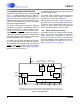
13. HARDWARE MODE DESCRIPTION
Hardware mode is selected by connecting the H/S
pin to ‘1’. Hardware Mode data flow is shown in
Figure 19. Audio data is input through the AES3 re-
ceiver, and routed to the serial audio output port.
Different audio data synchronous to RMCK may be
input into the serial audio input port, and output
through the AES3 transmitter.
The channel status data, user data and validity bit
information are handled in 2 alternative modes: A
and B, determined by a start-up resistor on the
COPY pin. In mode A, the received PRO, COPY,
ORIG, EMPH
, and AUDIO channel status bits are
output on pins. The transmitted channel status bits
are copied from the received channel status data,
and the transmitted U and V bits are 0.
In mode B, only the COPY and ORIG pins are out-
put, and reflect the received channel status data.
The transmitted channel status bits, user data and
validity bits are input serially through the PRO/C,
EMPH
/U and AUDIO/V pins. Figure 13 on page 22
shows the timing requirements.
The APMS pin allows the serial audio input port to
be set to master or slave.
If a validity, parity, bi-phase or lock receiver error
occurs, the current audio sample is passed un-
modified to the serial audio output port.
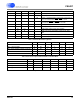
Start-up options are shown in Table 2 on page 43,
and allow choice of the serial audio output port as
a master or slave, whether TCBL is an input or an
output, the audio serial ports formats and the
source of the transmitted C, U and V data.
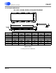
13.1 Serial Audio Port Formats
In hardware mode, only a limited number of alter-
native serial audio port formats are available.
These formats are described by Table 3 on
page 43 and Table 4 on page 43, which define the
equivalent software mode bit settings for each for-
mat. Timing diagrams are shown in Figure 15 on
page 23 and Figure 16 on page 24.
AES3
Encoder
&Tx
Serial
Audio
Output
AES3 Rx
&
Decoder
C&UbitDataBuffer
RXP
RXN
OLRCK
OSCLK
SDOUT
TXP
TXN
RMCK
RERR COPY ORIG EMPH/U
AUDIO/V
TCBL
VL+
H/S
Power supply pins (VD+, VA+, DGND, AGND) & the reset pin (RST) and the PLL filter pin (FILT)
are omitted from this diagram. Please refer to the Typical Connection Diagram for hook-up details.
Serial
Audio
Input
ILRCK
ISCLK
SDIN
PRO/C
APMS
Figure 19. Hardware Mode