
User Manual


CS8427
DS477F5 41
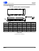
TXP
TXN
25
26
Differential Line Driver (Output) - Drivers transmit AES3 data and are pulled low while the
CS8427 is in the reset state.
AD1/CDIN 27 Address Bit 1 (I²C) / Serial Control Data in (SPI) (Input) - In I²C mode, AD1 is a chip
address pin. In SPI mode, CDIN is the input data line for the control port interface
SCL/CCLK 28 Control Port Clock (Input) - Serial control interface clock and is used to clock control data
bits into and out of the CS8427. In I²C mode, SCL requires an external pull-up resistor to
VL+