
User Manual


CS8427
26 DS477F5
mode is used for active-low, wired-OR hook-ups
with multiple peripherals connected to the micro-
controller interrupt input pin.
Many conditions can cause an interrupt, as listed in
the interrupt status register descriptions. Each
source may be masked off using mask register
bits. In addition, each source may be set to rising
edge, falling edge, or level-sensitive. Combined
with the option of level-sensitive or edge-sensitive
modes within the microcontroller, many different
set-ups are possible depending on the needs of
the equipment designer.
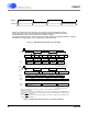
MAP
MSB
LSB
DATA
byte 1
byte n
R/W
R/W
ADDRESS
CHIP
ADDRESS
CHIP
CDIN
CCLK
CS
CDOUT
MSB
LSB
MSB
LSB
0010000
0010000
MAP = Memory Address Pointer, 8 bits, MSB first
High Impedance
Figure 17. Control Port Timing in SPI Mode
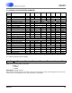
SDA
SCL
0010
AD2-0
R/W
Start
ACK
DATA7-0
ACK
DATA7-0
ACK
Stop
Note 2
Note 1
Note 1: AD2 is derived from a resistor attached to the EMPH pin,
Note 2: If operation is a write, this byte contains the Memory Address Pointer, MAP
AD1 and AD0 are determined by the state of the corresponding pins
Note 3: If operation is a read, the last bit of the read should be a NACK(high)
Note 3
Figure 18. Control Port Timing in I²C Mode