
User Manual


CS8427
22 DS477F5
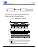
VLRCK
U (Out)
VLRCK is a virtual word clock, which may not exist, but is used to illustrate the U timing.
VLRCK duty cycle is 50%. VLRCK frequency is always equal to the incoming frame rate.
If the serial audio output port is in master mode, VLRCK = OLRCK.
If the serial audio output port is in slave mode, then VLRCK needs to be externally created, if required.
U transitions are aligned within 1% of VLRCK period to VLRCK edges
±
Figure 13. AES3 Receiver Timing for U pin output data
VCU[0] VCU[1] VCU[2] VCU[3] VCU[4]
VLRCK
Data [4] Data [5] Data [6] Data [7] Data [8]
Data [0] Data [1] Data [2] Data [3] Data [4]
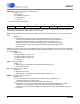
TXP(N)
Z Y X Y X
AES3 Transmitter in Stereo Mode
U[0] U[2]
TCBL
In or Out
VLRCK
U
Input
Data [4] Data [5] Data [6] Data [7] Data [8]
SDIN
Input
Data [0]* Data [2]* Data [4]*
TXP(N)
Output
Z Y X
* Assume MMTLR = 0
Tsetup => 7.5% AES3 frame time
Thold = 0
Tsetup
Thold
Data [1]* Data [3]* Data [5]*
TXP(N)
Output
ZYX
AES3 Transmitter in Mono Mode
* Assume MMTLR = 1
Tsetup => 15% AES3 frame time
Thold = 0
VLRCK is a virtual word clock, which may not exist, is used to illustrate the CUV timing.
VLRCK duty cycle is 50%.
In stereo mode, VLRCK frequency = AES3 frame rate. In mono mode, ALRCK frequency = 2xAES3 frame rate.
If the serial audio input port is on slave mode and TCBL is an output, then VLRCK=ILRCK if SILRPOL=0 and
VLRCK= ILRCK if SILRPOL =1.
If the serial audio input port is in master mode and TCBL is an input, then VLRCK=ILRCK if SILRPOL=0 and
VLRCK= ILRCK if SILRPOL =1.
Tth
Tth > 3OMCK if TCBL is Input
Tth > 3OMCK if TCBL is Input
Tth
Figure 14. AES3 Transmitter Timing for C, U and V pin input data