
Manual

34 DS641F6
CS8421
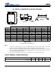
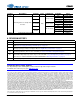
1. Dimensioning and tolerance per ASME Y 14.5M-1995.
2. Dimensioning lead width applies to the plated terminal and is measured between 0.23mm and 0.33mm from the
terminal tip.
QFN THERMAL CHARACTERISTICS
INCHES MILLIMETERS NOTE
DIM MIN NOM MAX MIN NOM MAX
A -- -- 0.0394 -- -- 1.00 1
A1 0.0000 -- 0.0020 0.00 -- 0.05 1
b 0.0091 0.0110 0.0130 0.23 0.28 0.33 1, 2
D 0.1969 BSC 5.00 BSC 1
D2 0.1201 0.1220 0.1240 3.05 3.10 3.15 1
E 0.1969 BSC 5.00 BSC 1
E2 0.1202 0.1221 0.1241 3.05 3.10 3.15 1
e 0.0256 BSC 0.65 BSC 1
L 0.0197 0.0236 0.0276 0.50 0.60 0.70 1
JEDEC #: MO-220
Controlling Dimension is Millimeters.
Parameter Symbol Min Typ Max Units
Junction to Ambient Thermal Impedance 2 Layer Board
4 Layer Board
JA
-
-
128
35
-
-
°C/Watt
°C/Watt
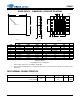
Side View
A
A1
D2
L
b
e
Pin #1 Corner
Bottom View
Top View
Pin #1 Corner
D
E
E2
20-PIN QFN (5 5 MM BODY) PACKAGE DRAWING