
Manual

DS641F6 15
CS8421CS8421
CS8421
VD VL
Serial
Audio
Source
ILRCK
ISCLK
SDIN
BYPASS
+2.5 V +3.3 V or +5.0 V
0.1 F0.1 F
Serial
Audio
Input
Device
OLRCK
OSCLK
SDOUT
XTI
XTO
RST
SRC_UNLOCK
SAOF
TDM_IN
Hardware Control
Settings
Crystal /Clock
Source
GND
SAIF
MS_SEL
GND
MCLK_OUT
To external
hardware
47 k
* **
***
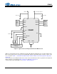
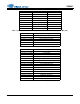
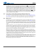
Figure 6. Typical Connection Diagram, Master and Slave Modes
* The connection (VL or GND) and value of these three resistors determines the mode of operation for the input
and output serial ports as described in Table 1 Serial Audio Port Master/Slave and Clock Ratio Select Start-Up Op-
tions (MS_SEL), and Table 2, “Serial Audio Input Port Start-Up Options (SAIF),” on page 18 and Table 3, “Serial
Audio Output Port Start-Up Options (SAOF),” on page 18.
** MCLK_OUT pin should be pulled high through a 47 k
resistor if an MCLK output is not needed.
*** This pin must not be pulled high. See Section 1, “Pin Descriptions.”