
Manual

DS641F6 13
CS8421CS8421
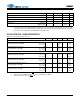
6. After powering up the CS8421, RST should be held low until the power supplies and clocks are settled.
7. The maximum possible sample rate is XTI/128.
8. OLRCK must remain high for at least 8 OSCLK periods in TDM Mode.
9. Only the input or the output serial port can be set as master at a given time.
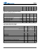
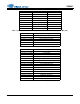
Master Mode (Note 9)
I/OSCLK Frequency (non-TDM) 64*Fsi/o MHz
OSCLK Frequency (TDM) 256*Fso MHz
I/OLRCK Duty Cycle 45 55 %
I/OSCLK Duty Cycle 45 55 %
I/OSCLK Falling Edge to I/OLRCK Edge t
lcks
-5ns
OSCLK Falling Edge to OLRCK Edge (TDM) t
fss
-5ns
OSCLK Falling Edge to SDOUT Output Valid t
dpd
-7ns
SDIN/TDM_IN Setup Time Before I/OSCLK Rising Edge t
ds
3-ns
SDIN/TDM_IN Hold Time After I/OSCLK Rising Edge t
dh
5-ns
Parameters Symbol Min Max Units
t
ds
OLRCK
(input)
t
dh
t
sckh
t
sckl
t
fsh
t
fss
OSCLK
(input)
TDM_IN
(input)
SDOUT
(output)
MSB
t
dpd
MSB-1
MSB
MSB-1
t
lrckh
t
ds
MSB
t
dh
t
dpd
MSB-1
I/OLRCK
(input)
I/OSCLK
(input)
SDIN
(input)
SDOUT
(output)
MSB
MSB-1
t
sckh
t
sckl
t
lcks
t
lckd
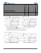
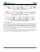
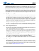
Figure 1. Non-TDM Slave Mode Timing Figure 2. TDM Slave Mode Timing
t
ds
OLRCK
(output)
t
dh
t
dpd
t
fss
OSCLK
(output)
TDM_IN
(input)
SDOUT
(output)
MSB
MSB-1
MSB
MSB-1
t
ds
MSB
t
dh
t
dpd
MSB-1
t
lcks
I/OLRCK
(output)
I/OSCLK
(output)
SDIN
(input)
SDOUT
(output)
MSB
MSB-1
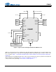
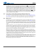
Figure 3. Non-TDM Master Mode Timing Figure 4. TDM Master Mode Timing