
User guide

DS578F3 57
CS8416
Notes:
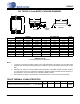
1. “D” and “E1” are reference datums and do not include mold flash or protrusions, but do include mold
mismatch and are measured at the parting line, mold flash or protrusions shall not exceed 0.20 mm per
side.
2. Dimension “b” does not include dambar protrusion/intrusion. Allowable dambar protrusion shall be
0.13 mm total in excess of “b” dimension at maximum material condition. Dambar intrusion shall not re-
duce dimension “b” by more than 0.07 mm at least material condition.
3. These dimensions apply to the flat section of the lead between 0.10 and 0.25 mm from lead tips.
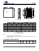
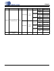
TSSOP THERMAL CHARACTERISTICS
INCHES MILLIMETERS NOTE
DIM MIN NOM MAX MIN NOM MAX
A -- --0.47-- --1.20
A1 0.002 0.004 0.006 0.05 0.10 0.15
A2 0.03150 0.035 0.04 0.80 0.90 1.00
b 0.00748 0.0096 0.012 0.19 0.245 0.30 2,3
D 0.378 BSC 0.382 BSC 0.386 BSC 9.60 BSC 9.70 BSC 9.80 BSC 1
E 0.248 0.2519 0.256 6.30 6.40 6.50
E1 0.169 0.1732 0.177 4.30 4.40 4.50 1
e -- 0.026 BSC -- -- 0.65 BSC --
L 0.020 0.024 0.029 0.50 0.60 0.75
µ
0° 4° 8° 0° 4° 8°
JEDEC #: MO-153
Controlling Dimension is Millimeters.
Parameter Symbol Min Typ Max Units
Junction to Ambient Thermal Impedance 4 Layer Board θ
JA
-
40
-°C/Watt
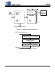
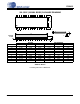
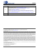
28L TSSOP (4.4 mm BODY) PACKAGE DRAWING
E
N
1
23
e
b
2
A1
A2
A
D
SEATING
PLANE
E1
1
L
SIDE VIEW
END VIEW
TOP VIEW
∝