
User guide

46 DS578F3
CS8416
15.HARDWARE MODE
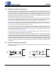
The CS8416 has a Hardware Mode that allows the device to operate without a microcontroller. Hardware Mode is
selected by connecting the 47 k
Ω pull-up/down resistor on the SDOUT pin to ground. Various pins change function
in Hardware Mode, described in Section 15.2 “Hardware Mode Function Selection” on page 46.
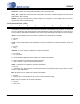
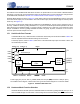
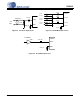
Hardware Mode data flow is shown in Figure 15. Audio data is input through the AES3/SPDIF receiver, and routed
to the serial audio output port. The decoded C and U bits are also output, clocked at both edges of OLRCK (master
mode only, see Figure 10).
An error in the incoming audio stream will be indicated on the NV/RERR pin. This pin can be configured in one of
two ways. If RERR is chosen by pulling NV/RERR to VL, the previous audio sample is held and passed to the serial
audio output port if the validity bit is high, or a parity, bi-phase, confidence or PLL lock error occurs during the current
sample. If NVERR is chosen by pulling NV/RERR to DGND, only parity, bi-phase, confidence or PLL lock error
cause the previous audio sample to be held.
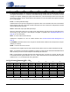
15.1 Serial Audio Port Formats
In Hardware Mode, only a limited number of alternative serial audio port formats are available. Table 5 de-
fines the equivalent Software Mode bit settings for each format.
The start-up options, shown in Table 4, allow choice of the serial audio output port as a master or slave, and
the serial audio port format.
15.2 Hardware Mode Function Selection
Hardware Mode and several options for Hardware Mode are selected by pulling CS8416 pins up to VL or
down to DGND through a 47 k
Ω resistor. These settings are sensed immediately after RST is released. For
NV/RERR
Power supply pins (VA, VD, and VL), AGND, DGND, the reset pin (RST) and the PLL filter pin (FILT)
are omitted from the diagram. Please refer to the Typical Connection Diagram for connection details.
RXP1
4:2
MUX
RXP2
RXP3
RXP0
96kHzRMCK
RXSEL[1:0] TXSEL[1:0]
AUDIO RCBL
RXN
AES3 Rx
&
Decoder
OMCK
TX
OLRCK
OSCLK
SDOUT
C
U
De-emphasis
Filter
Serial
Audio
Output
TX Passthrough
Figure 15. Hardware Mode Data Flow