
User guide

DS578F3 29
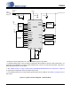
CS8416
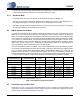
9. GENERAL PURPOSE OUTPUTS
Three General Purpose Outputs (GPO) are provided to allow the equipment designer flexibility in configuring the
CS8416. Fourteen signals are available to be routed to any of the GPO pins. The outputs of the GPO pins are set
through the GPOxSEL[3:0] bits in the Control2 (02h) and Control3 (03h) registers. All GPO pins default to GND
after reset.
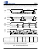
GPO pins may be configured to provide the following data:
Notes:
1. Frequency = 25 MHz Max, duty cycle not guaranteed, target duty cycle = 50% @ F
S
= 48 kHz.
Function Code Definition
GND 0000 Fixed low level
EMPH 0001 State of EMPH bit in the incoming data stream.
INT 0010 CS8416 interrupt output
C 0011 Channel status bit
U 0100 User data bit
RERR 0101 Receiver Error
NVERR 0110 Non-Validity Receiver Error
RCBL 0111 Receiver Channel Status Block
96KHZ 1000
If the input sample rate is ≤ 48 kHz, outputs a “0”. Outputs a “1” if the sample rate is ≥ 88.1 kHz.
Otherwise the output is indeterminate.
AUDIO 1001 Non-audio indicator for decoded input stream
VLRCK 1010 Virtual LRCK. Can be used to frame the C and U output data.
TX 1011 Pass through of AES/SPDIF input selected by TXSEL[2:0] in the Control 4 register (04h)
VDD 1100 VDD fixed high level
HRMCK 1101
F
S
X 512
(Note 1)
Codes 1110 to 1111 - Reserved
Table 3. GPO Pin Configurations