
Manual

6 DS470F4
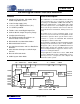
CS8415A
1. CHARACTERISTICS AND SPECIFICATIONS
All Min/Max characteristics and specifications are guaranteed over the Specified Operating Conditions. Typical per-
formance characteristics and specifications are derived from measurements taken at nominal supply voltages and
T
A
= 25°C.
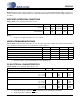
SPECIFIED OPERATING CONDITIONS
AGND, DGND = 0 V, all voltages with respect to 0 V.
Notes:
1. I²C protocol is supported only in VL+ = 5.0 V mode.
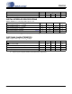
ABSOLUTE MAXIMUM RATINGS
AGND, DGND = 0 V; all voltages with respect to 0 V. Operation beyond these limits may result in permanent dam-
age to the device. Normal operation is not guaranteed at these extremes.
2. Transient currents of up to 100 mA will not cause SCR latch-up.
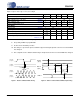
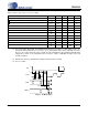
DC ELECTRICAL CHARACTERISTICS
AGND = DGND = 0 V; all voltages with respect to 0 V.
3. Power Down Mode is defined as RST
= LO with all clocks and data lines held static.
4. Normal operation is defined as RST
= HI.
Parameter Symbol Min Typ Max Units
Power Supply Voltage
(Note 1)
VA+
VL+
4.5
2.85
5.0
3.3 or 5.0
5.5
5.5
V
V
Ambient Operating Temperature: Commercial Grade
Industrial Grade
T
A
-10
-40
-
-
+70
+85
°C
Parameter Symbol Min Max Units
Power Supply Voltage
VL+,VA+ - 6.0 V
Input Current, Any Pin Except Supplies (Note 2)
I
in
-±10mA
Input Voltage
V
in
-0.3 (VL+) + 0.3 V
Ambient Operating Temperature (power applied)
T
A
-55 125 °C
Storage Temperature
T
stg
-65 150 °C
Parameters Symbol Min Typ Max Units
Power-down Mode (Note 3)
Supply Current in power down VA+
VL+ = 3.3 V
VL+ = 5.0 V
-
-
-
20
60
60
-
-
-
µA
µA
µA
Normal Operation (Note 4)
Supply Current at 48 kHz frame rate VA+
VL+ = 3.3 V
VL+ = 5.0 V
-
-
-
6.3
30.1
46.5
-
-
-
mA
mA
mA
Supply Current at 96 kHz frame rate VA+
VL+ = 3.3 V
VL+ = 5.0 V
-
-
-
6.6
44.8
76.6
-
-
-
mA
mA
mA