
Manual

32 DS470F4
CS8415A
10.HARDWARE MODE
The CS8415A has a hardware mode which allows using the device without a microcontroller. Hardware mode is
selected by connecting the H/S
pin to VL+. Various pins change function in hardware mode, described in the hard-
ware mode pin definition section.
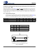
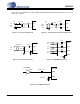
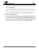
Hardware mode data flow is shown in Figure 10. Audio data is input through the AES3 receiver, and routed to the
serial audio output port. The PRO, COPY, ORIG, EMPH
, and AUDIO channel status bits are output on pins. The
decoded C and U bits are also output, clocked at both edges of OLRCK (master mode only, see Figure 7).The cur-
rent audio sample is passed unmodified to the serial audio output port if the validity bit is high, or a parity, bi-phase,
or PLL lock error occurs.
10.1 Serial Audio Port Formats
In hardware mode, only a limited number of alternative serial audio port formats are available. Table 2 de-
fines the equivalent software mode bit settings for each format. Start-up options are shown in Table 3, and
allow choice of the serial audio output port as a master or slave, and the serial audio port format.
SOSF SORES1/0 SOJUST SODEL SOSPOL SOLRPOL
OF1 - Left Justified 0 00 0 0 0 0
OF2 - I²S 24-bit data 0 00 0 1 0 1
OF3 - Right Justified, master mode only 0 00 1 0 0 0
OF4 - Direct AES3 data 0 11 0 0 0 0
Table 2. Equivalent Software Mode Bit Definitions
SDOUT ORIG EMPH Function
LO - - Serial Output Port is Slave
HI - - Serial Output Port is Master
- LO LO Left Justified
- LO HI I²S 24-bit data
- HI LO Right Justified
- HI HI Direct AES3 data
Table 3. Hardware Mode Start-Up Options
Serial
Audio
Output
AES3 Rx
&
Decoder
C & U bit Data Buffer
RXP
RXN
OLRCK
OSCLK
SDOUT
RMCK RERR
COPY ORIG EMPH RCBLPRO AUDIO
CHS
H/S
Power supply pins (VD+, VA+, DGND, AGND) & the reset pin (RST) and the PLL filter pin (FILT)
are omitted from this diagram. Please refer to the Typical Connection Diagram for hook-up details.
VL+
NVERR
C
U
Figure 10. Hardware Mode