
Instruction Manual
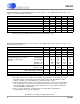

POWER SUPPLY SPECIFICATIONS (TA = 25°C; V+ = 3.0V, Digital Input Levels: Logic 0 = 0V, Logic 1 = V+,
Note 7)
Parameter Symbol Min Typ Max Units
Power Supply Voltage 2.7 3.0 5.5 V
Power Supply Current - All functions enabled (Note 8) - - 2.5 mA
Power Supply Current - All functions disabled (Note 9) - - 1
µA
Power Supply Current - Receiver only enabled (Note 8) - - 2.5 mA
Power Supply Current - Transmit only enabled (Note 10) - - 0.5 mA
Oscillator Power Supply Current low power mode:
normal power mode:
-
-
-
-
0.5
1.5
mA
mA
Data & State Retention Supply Voltage 2 - - V
Notes: 7. Power supply current specifications are with the supply at 3.0V. For approximate consumption at
+5.0V, multiply the above currents by 1.667.
8. Oscillator in low power mode, does not include LED current. Subtract oscillator current if using
an external clock to run the CS8130.
9. Floating digital inputs will not cause the power supply to increase beyond the specification.
10. Does not include LED current, does include oscillator current in low power mode.
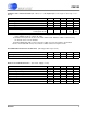
RECOMMENDED OPERATING CONDITIONS (All voltages with respect to 0V)
Parameter Symbol Min Typ Max Units
Operating Ambient Temperature T
A
02570
°C
Data and State Retention Temperature (In Power Down) -40 - 85
°C
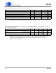
DIGITAL PIN CHARACTERISTICS (TA = 25°C, Supply = 3.0V)
Parameter Symbol Min Typ Max Units
High-level Input Voltage V
IH
2.0 - - V
Low-level Input Voltage V
IL
--0.8V
High-level Output Voltage at I
O
= -2.0mA V
OH
VD-0.3 - - V
Low-level Output Voltage at I
O
= 2.0mA V
OL
--0.3V
Output Leakage Current in Hi-Z state 0.2
µA
Input Leakage Current (Digital Inputs) - - 0.2
µA
Output Capacitance C
OUT
-5-pF
Input Capacitance C
IN
-5-pF
CS8130
DS134PP2 3
CS8130
DS134F1 3