
Instruction Manual

44
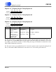
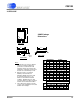
20 PIN SSOP
28 PIN SSOP
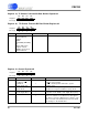
E
A
A
D
E
A
1
1
SIDE VIEW
END VIEW
TOP VIEW
Seating
Plane
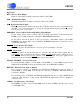
Notes:
1. "D" and "E " are reference datums
and do not include mold flash or
protrusions, but do include mold
mismatch and are measured at the
parting line, mold flash or protrusions
shall not exceed 0.20mm per side.
2. Dimension b does not include
dambar protrusion/intrusion.
Allowable dambar protrusion shall
be 0.13mm total in excess of b
dimension at maximum material
condition. Dambar intrusion shall
not reduce dimension b by more than
0.07mm at least material condition.
3. These dimensions apply to the flat
section of the lead between 0.10 and
0.25mm from lead tips.
N
132
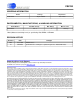
SSOP Package
Dimensions
N
MILLIMETERS
MIN NOM MAX
20
28
6.90 7.20 7.50
9.90 10.20 10.50
Note
1
1
1
2
1
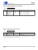
∝
DIM
MILLIMETERS
MIN NOM MAX
A
A
A
b
D
E
e
E
L
N
-
-
2.13
0.05 0.15 0.25
1.62 1.75 1.88
0.22 0.30 0.38
see other table
5.00 5.30 5.60
7.40 7.80 8.20
0.63 0.90 1.03
see other table
0°4° 8°
Note
2, 3
1
1
1
2
1
e
b
2
0.61 0.65 0.69
L
INCHES
MIN NOM MAX
-
-
0.084
0.002
0.006
0.010
0.064
0.070
0.074
0.009
0.012
0.015
see other table
0.197
0.209
0.220
0.291
0.307
0.323
0.025
0.035
0.040
see other table
0° 4° 8°
0.024
0.026
0.027
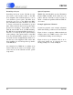
D
INCHES
MIN NOM MAX
0.272
0.283
0.295
0.390 0.402 0.413
1
CS8130
DS134F1 27