
User guide

CS6422
11
of higher amplitude will clip the ADC input and
will result in poor echo canceller performance. See
Section 4., “Design Considerations” for more de-
tails.
The outputs are delta-sigma digital to analog con-
verters (DACs) and have similar requirements to
the ADCs. The DACs are pre-compensated to ex-
pect a single-pole RC filter with a corner frequency
at 4 kHz. The full scale voltage output from a DAC
is 1.1 V
rms
(3.1 V
pp
) maximum, 1 V
rms
typical, bi-
ased around 2.12 VDC.
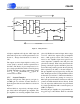
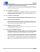
3.1.1 Acoustic Interface
The pins API (pin 20), APO (pin 18), AO (pin 3),
and MB (pin 19) form the Acoustic Interface. A
block diagram of the Acoustic Interface is shown in
Figure 6.
API and APO are, respectively, the input and out-
put of the built-in microphone pre-amplifier. The
pre-amplifier is an inverting amplifier with a fixed
gain of 34 dB biased around an input offset voltage
of 2.12 V. APO is the output of the pre-amplifier
after a 1 kΩ (typical) resistor. The circuitry con-
nected to the amplifier input must present low
source impedance (<100 Ω) to the API pin or the
gain will be reduced. When using the internal mic
preamp, a 0.022 µF capacitor should be placed be-
tween APO and ground to provide the anti-aliasing
filter required by the ADC, as shown in Figure 4.
The pre-amplifier may be bypassed by clearing the
‘Mic’ bit (Register 0, bit 15) using the Microcontrol-
ler Interface (see Section 3.2, “Microcontroller Inter-
face”). If the internal mic preamp is not used, a
0.022 µF capacitor should be tied between API and
ground, and APO should be driven directly. In this
case, the signal into APO must be low-pass filtered
by a single-pole RC filter with a corner frequency at
8 kHz (see Figure 5).
Following the pre-amplifier is a programmable an-
alog gain stage, called TGain, which is controlled
MBAPO
20
AO
(0,6,9.5,12 dB)
ADC
DAC
DAC
ADC
D
S
P
NI
17
NO
4
FAR-END
Transmit Path
Receive Path
API
1k
Ω
Voltage
Reference
34 dB
(0,6,9.5,12 dB)
NEAR-END
3
TGain
RGain
CS6422
Mic
1918
Figure 6. Analog Interface
CS6422
DS295F1 11