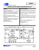
CS6422 CS6422 Enhanced Enhanced Full-Duplex Full-duplex Speakerphone Speakerphone IC IC Features General Description l Single-chip, Most modern speakerphones use half-duplex operation, which alternates transmission between the far-end talker and the speakerphone user. This is done to ensure stability because the acoustic coupling between the speaker and microphone is much higher in speakerphones than in handsets where the coupling is mechanically suppressed.
CS6422 TABLE OF CONTENTS 1. CHARACTERISTICS AND SPECIFICATIONS ........................................................................ 5 ABSOLUTE MAXIMUM RATINGS ........................................................................................... 5 RECOMMENDED OPERATING CONDITIONS ....................................................................... 5 POWER CONSUMPTION ........................................................................................................
CS6422 3.5.4 HDly - Half-Duplex Holdover Delay......................................................................... 19 3.5.5 HHold - Hold in Half-Duplex on Howl ...................................................................... 19 3.5.6 TDSRmp - Tx Double-talk Suppression Ramp rate ................................................ 19 3.5.7 RDSRmp - Rx Double-talk Suppression Ramp rate ............................................... 20 3.5.8 IdlTx - half-duplex Idle return-to-Transmit ................
CS6422 4.1.4.3 Double-talk Attenuation ....................................................................... 36 4.1.4.4 Noise Guard ........................................................................................ 37 4.2 Circuit Design ................................................................................................................... 37 4.2.1 Interface Considerations ..................................................................................... 37 4.2.1.1 Analog Interface ...
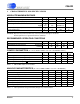
CS6422 1. CHARACTERISTICS AND SPECIFICATIONS ABSOLUTE MAXIMUM RATINGS Parameter Symbol Min Max Units -0.3 6.0 V Iin -10 +10 mA Vina Vind -0.3 -0.3 AVDD+0.3 DVDD+0.3 V Ambient Operating Temperature TA -40 85 °C Storage Temperature Tstg -65 150 °C DC Supply (AVDD, DVDD) Input Current (Except supply pins) Input Voltage Analog Digital WARNING: Operation beyond these limits may result in permanent damage to the device. Normal operation is not guaranteed at these extremes.
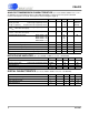
CS6422 ANALOG TRANSMISSION CHARACTERISTICS (TA = 25°C, DVDD = AVDD = 5 V, f XTAL = 20.
CS6422 ANALOG TRANSMISSION CHARACTERISTICS (TA = -40°C to 85oC, DVDD = AVDD = 5 V, f XTAL =20.
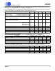
CS6422 SWITCHING CHARACTERISTICS Parameter Symbol Digital input rise time Min Typ trise tRSTL RST low time Units 1.0 µs 1.0 µs 20.480 CLKI frequency fCLKI CLKI duty cycle tLCLKI 40 CLKI high or low time tHLCLKI 19.5 Min DRDY falling to DRDY falling (CLKI = 20.
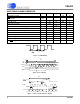
CS6422 ferrite bead +5V Analog 10 µF + 0.1 µF 16 DVDD AVDD 15 DGND AGND 1 0.1 µ F + 2 10 µF CS6422 19 MB 0.1 µF +10 µ F 12.1 kΩ Network Line Out 4 Mic Bias NO APO 18 3300 pF 0.022 µ F 0.47 µF 6.04 kΩ Network Line In 17 NI 3300 pF 20 API 8 7 6 5 From Microcontroller DATA STROBE 0.47 µF 12.1 kΩ 3 AO DRDY RST 3300pF NC4 NC3 NC2 NC1 12 11 10 CLKI 9 14 CLKO 20.480 MHz 13 22pF Speaker Driver 22pF Figure 4.
CS6422 2. OVERVIEW The CS6422 is a full-duplex speakerphone chip for use in hands-free communications with telephony quality audio. Common applications include speakerphones, inexpensive video-conferencing, and hands-free cellular phone car kits. The CS6422 requires very few external components and allows system control through a microcontroller interface.
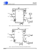
CS6422 Receive Path NI FAR-END NO 17 RGain ADC D S P (0,6,9.5,12 dB) 4 3 DAC DAC AO NEAR-END ADC 34 dB TGain Mic 20 API 1kΩ (0,6,9.5,12 dB) Voltage Reference CS6422 18 APO 19 MB Transmit Path Figure 6. Analog Interface of higher amplitude will clip the ADC input and will result in poor echo canceller performance. See Section 4., “Design Considerations” for more details. The outputs are delta-sigma digital to analog converters (DACs) and have similar requirements to the ADCs.
CS6422 through the Microcontroller Interface. This gain stage allows gains of 0 dB, 6 dB, 9.5 dB, and 12 dB to be added prior to the ADC input. The default gain stage setting is 0 dB. The signal at APO should not exceed 2.5 Vpp at the 0 dB gain stage setting. If a different gain setting is used, then the full-scale signal at APO must also change. Table 1 shows full-scale voltages as measured at APO for the given programmable gain: Gain Setting Full-scale Voltage 0 dB 2.5 Vpp 6 dB 1.25 Vpp 9.5 dB 0.
CS6422 STROBE pulses must be applied to latch the data into the CS6422. Since the MCR is a shift register, the STROBE can be run arbitrarily slowly with a duty cycle limited only by the minimum high and low time specified in “Switching Characteristics”. The Microcontroller Interface is polled at 125 µs intervals, so register writes must be spaced at least 125 µs apart or the register contents may be overwritten. 3.2.
CS6422 3.
CS6422 3.3.1 MIC - MICROPHONE PREAMPLIFIER ENABLE The microphone preamplifier described in Section 3.1.1, “Acoustic Interface” is enabled by default, but may be disabled by setting Mic to ‘0’. Refer to Section 3.1.1, “Acoustic Interface” for more details on using the Microphone Preamplifier. 3.3.2 HDD - HALF-DUPLEX DISABLE In normal operation, the CS6422 will be in a half-duplex mode if the echo canceller is not providing enough loop gain reduction to prevent howling.
CS6422 3.3.6 ACC - ACOUSTIC COEFFICIENT CONTROL The coefficients of the AEC adaptive filters in the CS6422 are controlled by ACC. The default position (00) yields normal operation, which means the coefficients are free to adjust themselves to the echo path in order to cancel echo. When set to the clear position (01), the adaptive filter coefficients are all held at zero, so the echo canceller is effectively disabled.
CS6422 3.
CS6422 3.4.1 THDET - TRANSMIT HALF-DUPLEX DETECTION THRESHOLD The sensitivity of the speech detector controls channel switching and ownership in half-duplex mode. The transmit speech detector registers speech if the transmit channel signal power is THDet above the noise floor of the transmit channel. 3.4.2 TAPS - AEC/NEC TAP ALLOCATION The CS6422 has a total of 63.5 ms of echo canceller taps that it can partition for use by the network and acoustic echo cancellers. By default, the CS6422 allocates 39.
CS6422 3.
CS6422 3.5.1 RHDET - RECEIVE HALF-DUPLEX DETECTION THRESHOLD The sensitivity of the speech detector controls channel switching and ownership in half-duplex mode. The receive speech detector registers speech if the receive channel signal power is RHDet above the noise floor for the receive channel. 3.5.2 RSTHD - RECEIVE SUPPRESSION THRESHOLD This parameter sets the threshold for far-end speech detection for disengaging receive suppression.
CS6422 3.5.7 RDSRMP - RX DOUBLE-TALK SUPPRESSION RAMP RATE When “Rx Double-talk Suppression attenuation” (RDbtS, Register 3) is set to a non-zero value, the CS6422 will introduce a programmable amount of attenuation into the receive path during a doubletalk event. RDSRmp controls the decay rate of the receive double-talk attenuation (the attack rate is ~40 ms). The ‘slow’ setting of RDSRmp results in an attenuation decay rate of about 1 second.
CS6422 3.6 Register 3 b15 b14 TSAtt 00 b13 PCSen 0 0 b12 b11 b10 TDbtS 000 b9 b8 RDbtS 00 b7 b6 TSThd 00 0 Bits 15-14 Name TSAtt Function Tx Suppression Attenuation 13 PCSen Path Change Sensitivity 12-10 TDbtS Tx Double-talk Suppression attenuation 9-8 RDbtS Rx Double-talk Suppression attenuation 7-6 TSThd Tx Suppression Threshold 5-4 TSBias Tx Suppression Bias b5 b4 TSBias 00 0 b3 0 b2 1 b1 1 b0 0 6 Word 00* 01 10 11 0* 1 000* 001 010 ...
CS6422 3.6.1 TSATT - TRANSMIT SUPPRESSION ATTENUATION This parameter sets the amount of attenuation inserted into the transmit path when transmit suppression is engaged. 3.6.2 PCSEN- PATH CHANGE SENSITIVITY The Acoustic Interface is likely to have many path changes as people move about in the room where the full-duplex speakerphone is being used. The sensitivity of the path change detector can be changed with the PCSen bit. Set PCSen to ‘0’ for high sensitivity and ‘1’ for low sensitivity.
CS6422 3.
CS6422 3.7.1 AERLE - AEC ERLE THRESHOLD The CS6422 will allow full-duplex operation when the ERLE provided by the AEC exceeds the value programmed at AErle. See also AFNse. See Section 6., “Glossary” for a definition of ERLE. 3.7.2 AFNSE - AEC FULL-DUPLEX NOISE THRESHOLD AFNse works in conjunction with AErle to determine when the CS6422 should transition into full-duplex operation. AFNse specifies a noise level.
CS6422 3.
CS6422 3.8.1 HWLD - HOWL DETECTOR DISABLE This is a diagnostic parameter that is normally set to ‘0’. In normal operation, the CS6422 will clear both the AEC and NEC coefficients, dropping the device into half-duplex operation, whenever an instability event is detected. Such an event can be caused by excessive loop gain, a major path change, or mistraining of the echo cancellers. Setting HwlD to ‘1’ prevents the instability detector from clearing the echo cancellers’ coefficients. 3.8.
CS6422 3.8.6 AECD - ACOUSTIC ECHO CANCELLER DISABLE Setting this bit to a ‘1’ disables the Acoustic Echo Canceller. The AEC is removed from the signal path and is not considered in the half/full-duplex decision making process. 3.8.7 NECD - NETWORK ECHO CANCELLER DISABLE Setting this bit to a ‘1’ disables the Network Echo Canceller. The NEC is removed from the signal path and is not considered in the half/full-duplex decision making process. 3.8.
CS6422 3.9 Reset A hardware reset, initiated by bringing RST low for at least tRSTL and then high again, must be applied after initial power-on. When RST is held low, the various internal blocks of the CS6422 are powered down. When RST is brought high, the oscillator is enabled and approximately 4 ms later, all digital clocks begin operating. The ADCs and DACs are calibrated and all internal digital initializations occur. The CS6422 supports two reset modes, cold reset and warm reset.
CS6422 3.11 Power Supply 3.11.1 The pins AVDD (pin 1) and AGND (pin 2) power the analog sections of the CS6422, and DVDD (pin 16) and DGND (pin 15) power the digital sections. This distinction is important because internal to the part, the digital power supply is likely to contain high-frequency energy. The analog power supply is kept clean internally by drawing current from a different pin, thereby achieving high performance in the codecs and the microphone preamplifier.
CS6422 Figure 8 shows the suggested placement of decoupling capacitors for the power supplies. Note that the trace length from the power pin to the capacitors is minimized. Also note that the smaller valued capacitor is placed closer to the pin than the larger valued capacitor. The smaller capacitor decouples high frequency noise and the larger capacitor attenuates lower frequencies. The separation of analog and digital power and ground is done in two ways.
CS6422 4. DESIGN CONSIDERATIONS 4.1.1.1 When designing the CS6422 into a system, it is important to keep several considerations in mind. These concerns can be loosely grouped into three categories: algorithmic considerations, circuit design considerations, and system design considerations. Figure 10 illustrates how the adaptive filter can cancel echo and reduce loop gain. The echo path of the system is between points B and C: the speaker to microphone coupling.
CS6422 room, when someone moves the speaker or the microphone, or when someone drops a piece of paper on top of the speaker. So, the filter needs to adapt to modify its transfer function to match that of the environment. It does so by measuring the error signal at point E and trying to minimize it. This signal is fed back to the adaptive filter to measure performance and how best to adapt, or train.
CS6422 characteristics than white noise because of its quasi-periodic nature. efit of suppressing the spurious taps mentioned in Section 4.1.1.2.1, “Pre-Emphasis”. Research at Crystal has shown that quasi-periodic signals cause the formation of spurious non-zero coefficients within the adaptive filter at tap intervals determined by the periodicity of the signal. This results in small changes in period being very destructive to the adaptive filter’s performance.
CS6422 14), and the receive suppression speech detector threshold is set by RSThd (Register 2, bits 13 and 12). The transmit speech detectors for both half-duplex and suppression default to 6 dB. Note that constant power signals which persist for long durations, such as tones or white noise from a signal generator, will be detected as speech only as long as the background noise level has not risen to within the speech detection threshold of the signal power.
CS6422 Fs Fs Fs 0dB 0dB 0dB -30dB -30dB -30dB (a) Input Signal t Fs (b) AGC Attenuation t (e) AGC Gain t (c) AGC Gain t Fs 0dB 0dB -30dB -30dB (d) Input Signal t Figure 11. How the AGC works (TVol = +30 dB) Any signal greater than 30 dB below full-scale (a), is scaled down to 30 dB (b). This signal is then scaled up +30 dB (the reference level) to provide the final output (c). Note that the combination of attenuation and gain results in less than +30 dB total gain being applied.
CS6422 Suppression may cause some modulation of the perceived background noise which may be distracting to some users. As a result, it may be desirable to limit the suppression attenuation to the minimum necessary. The CS6422 provides TSAtt (Register 3, bits 15 and 14) to control the amount of attenuation introduced by suppression in the transmit channel. Receive suppression attenuates by 24 dB. 4.1.4.
CS6422 loop (near-end speaker/mic to far-end speaker/mic) during a double-talk scenario (where both near-end and far-end parties are talking at the same time). The CS6422 implements an optional attenuation feature that introduces a programmable amount of loss in the transmit and/or receive directions during double-talk to alleviate stability concerns without sacrificing speaker volume. This allows for higher speaker volume levels at both ends of the call without compromising stability. 4.1.4.
CS6422 The three pins that comprise the Microcontroller Interface are STROBE, DATA, and DRDY. Also, four extra clocks are required after DRDY is brought high in order to latch the data into the CS6422, as is shown in Figure 7. The crystal oscillator should be placed as close as possible to reduce the distance that the high frequency signals must travel. If the crystal is placed too far away, the trace inductance may cause problems with oscillator startup. 4.2.
CS6422 speaker, the reflections reaching the microphone should present no more than 0.9 Vrms to the Acoustic ADC. In fact, it is advisable to allow 6 dB or even 12 dB of margin, such that in the above example, the signal present at the Acoustic ADC is 250 mVrms. After this coupling level is established, the desired signal gain must be established. To continue from the previous example, the transmit gain must be adjusted to make sure the near-end talker is easy to hear at the far-end.
CS6422 4.3.2.2 Convergence Time Convergence time is a measure of how quickly the adaptive filter can model the echo path. From cleared coefficients, the training signal is injected into the echo canceller and the time for the ERLE to reach a given threshold value is the convergence time. Different customers will have different threshold levels, so Crystal does not specify convergence time.
CS6422 5. PIN DESCRIPTIONS AVDD AGND AO NO RST DRDY STROBE DATA NC1 NC2 20 1 19 2 18 3 17 4 5 CS6422 16 15 6 7 14 8 13 12 9 11 10 API MB APO NI DVDD DGND CLKI CLKO NC4 NC3 Analog Interface AO - Acoustic Interface Output, Pin 3 Analog voltage output for the acoustic side (near-end output/receive output). Maximum output signal is 1.1 Vrms (3.1 Vpp). This output can drive down to 10 kΩ and is usually followed by a speaker driver.
CS6422 NI - Network Interface Input, Pin 17 Input to the network side analog-to-digital converter (far-end input/receive input). This input expects a single-pole RC anti-aliasing filter with a corner frequency of 8 kHz. Maximum signal level before clipping at this point is 0.9 Vrms (2.5 Vpp), assuming default settings for RGain. Microcontroller Interface RST - Active Low Reset Input, Pin 5 When RST is held low, the CS6422 is put into a low power mode with all functional blocks idle.
CS6422 Miscellaneous NC1 - No Connect, Pin 9 Must be floating for normal operation. NC2 - No Connect, Pin 10 Must be floating for normal operation. NC3 - No Connect, Pin 11 Must be floating for normal operation. NC4 - No Connect, Pin 12 Must be floating for normal operation.
CS6422 6. GLOSSARY Echo A signal that returns to its source after some delay. Network Echo Echo resulting from signal reflection due to an impedance mismatch in a 2-to-4 wire converter (hybrid). Acoustic Echo Echo created by signal propagation in a room from a speaker to a microphone. Reverberation Local information that bounces around the room before it reaches the microphone.
CS6422 Adaptive Filter A digital FIR filter that adjusts its coefficients to match a transfer function, such as the echo path between the speaker and microphone. The adaptive filter is able to compensate for different and changing conditions, such as someone moving in the room. Echo Path The acoustic echo path describes the acoustic coupling between the speaker and the microphone. It describes both the magnitude and delay characteristics of the echoed signal.
CS6422 7. PACKAGE DIMENSIONS 20L SOIC (300 MIL BODY) PACKAGE DRAWING E H 1 b c ∝ D L SEATING PLANE A e DIM A A1 b C D E e H L ∝ MIN 0.093 0.004 0.013 0.009 0.496 0.291 0.040 0.394 0.016 0° A1 INCHES NOM 0.098 0.008 0.017 0.011 0.504 0.295 0.050 0.407 0.025 4° MAX 0.104 0.012 0.020 0.013 0.512 0.299 0.060 0.419 0.050 8° MIN 2.35 0.10 0.33 0.23 12.60 7.40 1.02 10.00 0.40 0° MILLIMETERS NOM 2.50 0.20 0.43 0.28 12.80 7.50 1.27 10.34 0.64 4° MAX 2.65 0.30 0.51 0.32 13.00 7.60 1.52 10.65 1.
CS6422 ORDERING INFORMATION Model Temperature Package CS6422-CS 0 to +70 °C CS6422-CSZ (Lead Free) 20-pin SOIC CS6422-IS -40 to +85 °C CS6422-ISZ (Lead Free) ENVIRONMENTAL, MANUFACTURING, & HANDLING INFORMATION Model Number Peak Reflow Temp MSL Rating* Max Floor Life CS6422-CS 240 °C 2 365 Days CS6422-CSZ (Lead Free) 260 °C 3 7 Days CS6422-IS 240 °C 2 365 Days CS6422-ISZ (Lead Free) 260 °C 3 7 Days * MSL (Moisture Sensitivity Level) as specified by IPC/JEDEC J-STD-020.