
Instruction Manual

CS61884
48 DS485F3
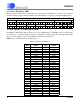
16.3 Device ID Register (IDR)
Revision section: 0h = Rev A, 1h = Rev B and so on. The device Identification Code [27 - 12] is derived
from the last three digits of the part number (884). The LSB is a constant 1, as defined by IEEE 1149.1.
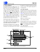
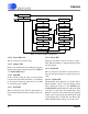
17. BOUNDARY SCAN REGISTER (BSR)
The BSR is a shift register that provides access to the digital I/O pins. The BSR is used to read and write
the device pins to verify interchip connectivity. Each pin has a corresponding scan cell in the register. The
pin to scan cell mapping is given in the BSR description shown in Table 11.
NOTE: Data is shifted LSB first into the BSR register.
CS61884 IDCODE REGISTER(IDR)
REVISION DEVICE IDCODE REGISTER MANUFACTURER CODE
31 30 29 28 27 26 25 24 23 22 21 20 19 18 17 16 15 14 13 12 11 109876543210
0h 0h 8h 8h 4h 0h Oh 9h
00000000100010000100000011001001
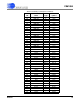
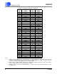
Table 11. Boundary Scan Register
BSR
Bit
Pin
Name
Cell
Type
Bit
Symbol
0 LOS7 O LOS7
1 RNEG7 O RNEG7
2 RPOS7 O RPOS7
3 RCLK7 O RCLK7
4 - Note 2 HIZ7_B
5 TNEG7 I TNEG7
6 TPOS7 I TPOS7
7 TCLK7 I TCLK7
8 LOS6 O LOS6_B
9 RNEG6 O RNEG6
10 RPOS6 O RPOS6
11 RCLK6 O RCLK6
12 - Note 2 HIZ6_B
13 TNEG6 I TNEG6
14 TPOS6 I TPOS6
15 TCLK6 I TCLK6
16 MCLK I MCLK
17 MODE I MODE_TRI
18 MODE I MODE_IN
19 ADDR4 I ADDR4
20 ADDR3 I ADDR3
21 ADDR2 I ADDR2
22 ADDR1 I ADDR1
23 ADDR0 I ADDR0
24 LOOP0/D0 I LPT0
25 LOOP0/D0 I LPI0
26 LOOP0/D0 O LPO0
27 LOOP1/D1 I LPT1