
Instruction Manual


CS61884
DS485F3 37
14.13 Digital Loopback Reset Register (0Ch)
14.14 LOS/AIS Mode Enable Register (0Dh)
14.15 Automatic TAOS Register (0Eh)
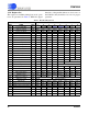
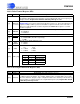
[3:0] A[3:0]
The G.772 Monitor is directed to a given channel based on the state of the four least signifi-
cant bits of this register. Register bits default to 00h after power-up or reset. The follow-
ing table shows the settings needed to select a specific channel’s receiver or transmitter to
perform G.772 monitoring.
A[3:0] Channel Selection
0000 Monitoring Disabled
0001 RX Channel #1
0010 RX Channel #2
0011 RX Channel #3
0100 RX Channel #4
0101 RX Channel #5
0110 RX Channel #6
0111 RX Channel #7
1000 Monitoring Disabled
1001 TX Channel #1
1010 TX Channel #2
1011 TX Channel #3
1100 TX Channel #4
1101 TX Channel #5
1110 TX Channel #6
1111 TX Channel #7
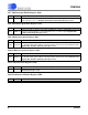
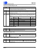
BIT NAME Description
[7:0] DLBK 7-0 Setting register bit n to “1” enables the digital loopback for channel n. Refer to Digital Loop-
back (See Section 12.3 on page 30) for a complete explanation. Register bits default to
00h after power-up or reset.
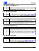
BIT NAME Description
[7:0] LAME 7-0 T1/J1 MODE
- These bits are “Do Not Care”, T1.231 Compliant LOS/AIS already used.
E1 Mode
- Setting bit n to “1” enables ETSI 300 233 compliant LOS/AIS for channel n; set-
ting bit n to “0” enables ITU G.775 compliant LOS/AIS for channel n. Register bits default to
00h after power-up or reset.
BIT NAME Description
[7:0] ATAO 7-0 Setting bit n to “1” enables automatic TAOS generation on channel n when LOS is detected.
Register bits default to 00h after power-up or reset.
(Continued)
BIT NAME Description