
Instruction Manual

CS61884
DS485F3 15
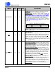
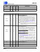
3.4 Cable Select
3.5
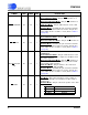
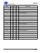
Status
SYMBOL LQFP LFBGA TYPE DESCRIPTION
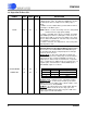
CBLSEL 93 G13 I
Cable Impedance Select
Host Mode
- The input voltage to this pin does not effect
normal operation.
Hardware Mode
- This pin is used in combination with the
LEN control pins (Refer to Table 5, “Hardware Mode Line
Length Configuration Selection,” on page 25) to set the line
impedance for all eight receivers and transmitters. This pin
also selects whether or not all eight receivers use an inter-
nal or external line matching network (Refer to the Table
below for proper settings).
NOTE: Refer to Figure 17 on page 51 and Figure 18 on
page 52 for appropriate external line matching com-
ponents. All transmitters use internal matching net-
works.
Table 3. Cable Impedance Selection
E1/T1/J1 CBLSEL Transmitters Receivers
T1/J1 No Connect 100 Ω Internal Internal
T1/J1 HIGH 100 Ω Internal Internal
T1/J1 LOW 100 Ω Internal External
E1 No Connect 120 Ω Internal Inter or Ext
E1 HIGH 75 Ω Internal Internal
E1 LOW 75 Ω Internal External
SYMBOL LQFP LFBGA TYPE DESCRIPTION
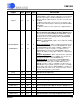
LOS0
LOS1
LOS2
LOS3
LOS4
LOS5
LOS6
LOS7
42
35
75
68
113
106
3
140
K4
K3
K12
K11
E11
E12
E3
E4
O
O
O
O
O
O
O
O
Loss of Signal Output
The LOS output pins can be configured to indicate a loss of
signal (LOS) state that is compliant to either T1.231, ITU
G.775 or ETSI 300 233. These pins are asserted “High” to
indicate LOS. The LOS output returns low when an input
signal is present for the time period dictated by the associ-
ated specification (Refer to Loss-of-Signal (LOS) (See
Section 10.5 on page 27)).