
User Manual
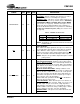
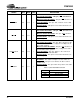
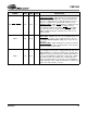
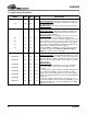
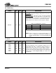
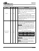
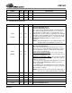
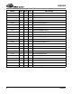
Table Of Contents
- Features
- Description
- 1. Pin Out - 144-Pin LQFP Package
- 2. Pin Out - 160-Ball FBGA Package
- 3. Pin Descriptions
- 4. operation
- 5. Power-up
- 6. Master Clock
- 7. G.772 Monitoring
- 8. Building Integrated Timing Systems (BITS) Clock Mode
- 9. Transmitter
- 10. Receiver
- 11. Jitter Attenuator
- 12. Operational Summary
- 13. Host Mode
- 14. Register Descriptions
- 14.1 Revision/IDcode Register (00h)
- 14.2 Analog Loopback Register (01h)
- 14.3 Remote Loopback Register (02h)
- 14.4 TAOS Enable Register (03h)
- 14.5 LOS Status Register (04h)
- 14.6 DFM Status Register (05h)
- 14.7 LOS Interrupt Enable Register (06h)
- 14.8 DFM Interrupt Enable Register (07h)
- 14.9 LOS Interrupt Status Register (08h)
- 14.10 DFM Interrupt Status Register (09h)
- 14.11 Software Reset Register (0Ah)
- 14.12 Performance Monitor Register (0Bh)
- 14.13 Digital Loopback Reset Register (0Ch)
- 14.14 LOS/AIS Mode Enable Register (0Dh)
- 14.15 Automatic TAOS Register (0Eh)
- 14.16 Global Control Register (0Fh)
- 14.17 Line Length Channel ID Register (10h)
- 14.18 Line Length Data Register (11h)
- 14.19 Output Disable Register (12h)
- 14.20 AIS Status Register (13h)
- 14.21 AIS Interrupt Enable Register (14h)
- 14.22 AIS Interrupt Status Register (15h)
- 14.23 AWG Broadcast Register (16h)
- 14.24 AWG Phase Address Register (17h)
- 14.25 AWG Phase Data Register (18h)
- 14.26 AWG Enable Register (19h)
- 14.27 Reserved Register (1Ah)
- 14.28 Reserved Register (1Bh)
- 14.29 Reserved Register (1Ch)
- 14.30 Reserved Register (1Dh)
- 14.31 Bits Clock Enable Register (1Eh)
- 14.32 Reserved Register (1Fh)
- 14.33 Status Registers
- 15. Arbitrary Waveform Generator
- 16. JTAG Support
- 17. Boundary Scan Register (BSR)
- 18. Applications
- 19. Characteristics and specifications
- 19.1 Absolute Maximum Ratings
- 19.2 Recommended Operating Conditions
- 19.3 Digital Characteristics
- 19.4 Transmitter Analog Characteristics
- 19.5 Receiver Analog Characteristics
- 19.6 Jitter Attenuator Characteristics
- 19.7 Master Clock Switching Characteristics
- 19.8 Transmit Switching Characteristics
- 19.9 Receive Switching Characteristics
- 19.10 Switching Characteristics - Serial Port
- 19.11 Switching Characteristics - Parallel Port (Multiplexed Mode)
- 19.12 Switching Characteristics- Parallel Port (Non-Multiplexed Mode)
- 19.13 Switching Characteristics - JTAG
- 20. Compliant Recommendations and specifications
- 21. 160-Ball FBGA package dimensions
- 22. 144-Pin LQFP Package dimensions
CS61880
DS450PP3 15
3.4 Cable Select
3.5
Status
SYMBOL LQFP FBGA TYPE DESCRIPTION
CBLSEL 93 G13 I
Cable Impedance Select
Host Mode
- The input voltage to this pin does not effect
normal operation.
Hardware Mode
- This pin is used to select the transmitted
pulse shape and set the line impedance for all eight receiv-
ers and transmitters. This pin also selects whether or not all
eight receivers use an internal or external line matching
network (Refer to the Table 4 below for proper settings).
NOTE: Refer to Figure 16 on page 50 and Figure 17 on
page 51 for appropriate external line matching com-
ponents. All transmitters use internal matching net-
works.
Table 4. Cable Impedance Selection
CBLSEL Transmitters Receivers
No Connect 120 Ω Internal 120 Ω Internal or External
HIGH 75 Ω Internal 75 Ω Internal
LOW 75 Ω Internal 75 Ω External
SYMBOL LQFP FBGA TYPE DESCRIPTION
LOS0
LOS1
LOS2
LOS3
LOS4
LOS5
LOS6
LOS7
42
35
75
68
113
106
3
140
K4
K3
K12
K11
E11
E12
E3
E4
O
O
O
O
O
O
O
O
Loss of Signal Output
The LOS output pins can be configured to indicate a loss of
signal (LOS) state that is compliant to either ITU G.775 or
ETSI 300 233. These pins are asserted “High” to indicate
LOS. The LOS output returns low when an input signal is
present for the time period dictated by the associated speci-
fication (Refer to Loss-of-Signal (LOS) (See Section 10.5
on page 27)).