
Instruction Manual
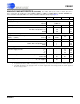
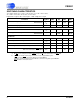
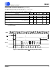
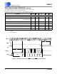
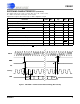
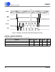
Table Of Contents
- Features & Description
- General Description
- Table of Contents
- List of Figures
- List of Tables
- 1. Characteristics and Specifications
- 2. Overview
- 3. Theory of Operation
- 3.1 Converter Operation
- 3.2 Clock
- 3.3 Voltage Reference
- 3.4 Analog Input
- 3.5 Output Coding Format
- 3.6 Typical Connection Diagrams
- 3.7 AIN & VREF Sampling Structures
- 3.8 Converter Performance
- 3.9 Digital Filter Characteristics
- 3.10 Serial Port
- 3.11 Power Supplies & Grounding
- 3.12 Using the CS5581 in Multiplexing Applications
- 3.13 Synchronizing Multiple Converters
- 4. Pin Descriptions
- 5. Package Dimensions
- 6. Ordering Information
- 7. Environmental, Manufacturing, & Handling Information
- 8. Revision History
CS5581
6 DS796PP1
3/25/08
14:34
SWITCHING CHARACTERISTICS
T
A
= -40 to +85 °C; V1+ = V2+ = +2.5 V, ±5%; V1- = V2- = -2.5 V, ±5%;
VL - VLR = 3.3 V, ±5%, 2.5 V, ±5%, or 1.8 V, ±5%
Input levels: Logic 0 = 0V = Low; Logic 1 = VD+ = High; CL = 15 pF.
8. Reset must not be released until the power supplies and the voltage reference are within specification.
9. BP/UP
can be changed coincident CONV falling. BP/UP must remain stable until RDY falls.
10. If CONV is held low continuously, conversions occur every 80 MCLK cycles.
If RDY
is tied to CONV, conversions will occur every 82 MCLKs.
If CONV is operated asynchronously to MCLK, a conversion may take up to 84 MCLKs.
RDY falls at the end of conversion.
Parameter Symbol Min Typ Max Unit
Master Clock Frequency Internal Oscillator
External Clock
XIN
f
clk
12
0.5
14
16
16
16.2
MHz
MHz
Master Clock Duty Cycle 40 - 60 %
Reset
RST
Low Time (Note 8) t
res
1--µs
RST
rising to RDY falling Internal Oscillator
External Clock
t
wup
-
-
120
1536
-
-
µs
MCLKs
Conversion
CONV
Pulse Width t
cpw
4--MCLKs
BP/UP
setup to CONV falling (Note 9) t
scn
0--ns
CONV
low to start of conversion t
scn
--2MCLKs
Perform Single Conversion (CONV
high before RDY falling) t
bus
20 - - MCLKs
Conversion Time (Note 10)
Start of Conversion to RDY
falling t
buh
- - 84 MCLKs