
Instruction Manual
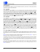
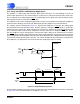
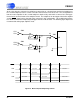

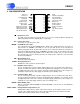
Table Of Contents
- Features & Description
- General Description
- Table of Contents
- List of Figures
- List of Tables
- 1. Characteristics and Specifications
- 2. Overview
- 3. Theory of Operation
- 3.1 Converter Operation
- 3.2 Clock
- 3.3 Voltage Reference
- 3.4 Analog Input
- 3.5 Output Coding Format
- 3.6 Typical Connection Diagrams
- 3.7 AIN & VREF Sampling Structures
- 3.8 Converter Performance
- 3.9 Digital Filter Characteristics
- 3.10 Serial Port
- 3.11 Power Supplies & Grounding
- 3.12 Using the CS5581 in Multiplexing Applications
- 3.13 Synchronizing Multiple Converters
- 4. Pin Descriptions
- 5. Package Dimensions
- 6. Ordering Information
- 7. Environmental, Manufacturing, & Handling Information
- 8. Revision History
CS5581
DS796PP1 27
3/25/08
14:34
3.13 Synchronizing Multiple Converters
Many measurement systems have multiple converters that need to operate synchronously. The convert-
ers should all be driven from the same master clock. In this configuration, the converters will convert syn-
chronously if the same CONV
signal is used to drive all the converters, and CONV falls on a falling edge
of MCLK. If CONV
is held low continuously, reset (RST) can be used to synchronize multiple converters
if RST
is released on a falling edge of MCLK.