
Instruction Manual
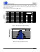
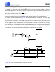
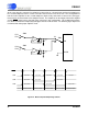
Table Of Contents
- Features & Description
- General Description
- Table of Contents
- List of Figures
- List of Tables
- 1. Characteristics and Specifications
- 2. Overview
- 3. Theory of Operation
- 3.1 Converter Operation
- 3.2 Clock
- 3.3 Voltage Reference
- 3.4 Analog Input
- 3.5 Output Coding Format
- 3.6 Typical Connection Diagrams
- 3.7 AIN & VREF Sampling Structures
- 3.8 Converter Performance
- 3.9 Digital Filter Characteristics
- 3.10 Serial Port
- 3.11 Power Supplies & Grounding
- 3.12 Using the CS5581 in Multiplexing Applications
- 3.13 Synchronizing Multiple Converters
- 4. Pin Descriptions
- 5. Package Dimensions
- 6. Ordering Information
- 7. Environmental, Manufacturing, & Handling Information
- 8. Revision History
CS5581
26 DS796PP1
3/25/08
14:34
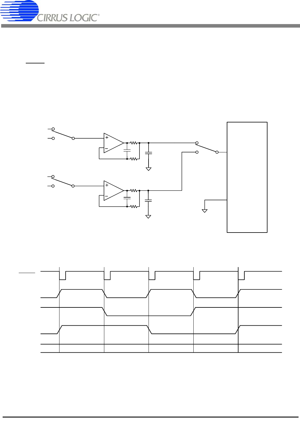
At the same time the converter is performing a conversion on a channel from one bank of multiplexers,
the second multiplexer bank is used to select the channel for the next conversion. This configuration al-
lows the buffer amplifier for the second multiplexer bank to fully settle while a conversion is being per-
formed on the channel from the first multiplexer bank. The multiplexer on the output of the buffer amplifier
and the CONV
signal can be changed at the same time in this configuration. This multiplexing architec-
ture allows for maximum multiplexing throughput from the A/D converter. The following figure depicts the
recommended analog input amplifier circuit.
Figure 22. More Complex Multiplexing Scheme
CS5581
AIN
ACOM
90
150pF
2k
4700pF
C0G
90
150pF
2k
CH1
CH3
CH2
CH4
SW2
SW3
SW1
A2
A1
4700pF
C0G
CONV
Convert on CH1 Convert on CH1Convert on CH4Convert on CH3Convert on CH2
Select A1 Select A2 Select A1 Select A2
Select CH1 Select CH3 Select CH1
Select A1
Select CH2 Select CH4 Select CH2
SW1
SW2
SW3