
Instruction Manual
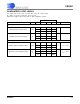
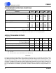
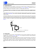
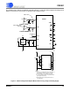
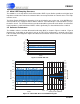
Table Of Contents
- Features & Description
- General Description
- Table of Contents
- List of Figures
- List of Tables
- 1. Characteristics and Specifications
- 2. Overview
- 3. Theory of Operation
- 3.1 Converter Operation
- 3.2 Clock
- 3.3 Voltage Reference
- 3.4 Analog Input
- 3.5 Output Coding Format
- 3.6 Typical Connection Diagrams
- 3.7 AIN & VREF Sampling Structures
- 3.8 Converter Performance
- 3.9 Digital Filter Characteristics
- 3.10 Serial Port
- 3.11 Power Supplies & Grounding
- 3.12 Using the CS5581 in Multiplexing Applications
- 3.13 Synchronizing Multiple Converters
- 4. Pin Descriptions
- 5. Package Dimensions
- 6. Ordering Information
- 7. Environmental, Manufacturing, & Handling Information
- 8. Revision History
CS5581
DS796PP1 13
3/25/08
14:34
2. OVERVIEW
The CS5581 is a 16-bit analog-to-digital converter capable of 200 kSps conversion rate. The analog input
accepts a single-ended input with a magnitude of ±VREF / 2
volts. The ADC uses a low-latency digital filter
architecture. The filter is designed for fast settling and settles to full accuracy in one conversion.
The converter is a serial output device. The serial port can be configured to function as either a master or
a slave.
The converter can operate from an analog supply of 5V or from ±2.5V. The digital interface supports stan-
dard logic operating from 1.8, 2.5, or 3.3 V.
The CS5581 may convert at rates up to 200 kSps when operating from a 16 MHz input clock.
3. THEORY OF OPERATION
The CS5581 converter provides high-performance measurement of DC or AC signals. The converter can
be used to perform single conversions or continuous conversions upon command. Each conversion is in-
dependent of previous conversions and settles to full specified accuracy, even with a full-scale input volt-
age step. This is due to the converter architecture which uses a combination of a high-speed delta-sigma
modulator and a low-latency filter architecture.
Once power is established to the converter, a reset must be performed. A reset initializes the internal con-
verter logic.
If CONV
is held low, the converter will convert continuously with RDY falling every 80 MCLKs. This is
equivalent to 200 kSps if MCLK = 16.0 MHz. If CONV
is tied to RDY, a conversion will occur every 82
MCLKs. If CONV
is operated asynchronously to MCLK, it may take up to 84 MCLKs from CONV falling to
RDY
falling.
Multiple converters can operate synchronously if they are driven by the same MCLK source and CONV
to each converter falls on the same MCLK falling edge. Alternately, CONV can be held low and all devices
can be synchronized if they are reset with RST
rising on the same falling edge of MCLK.
The output coding of the conversion word is a function of the BP/UP
pin.
3.1 Converter Operation
The converter should be reset after the power supplies and voltage reference are stable.
The CS5581 converts at 200 kSps when synchronously operated (CONV
= VLR) from a 16.0 MHz master
clock. Conversion is initiated by taking CONV
low. A conversion lasts 80 master clock cycles, but if CONV
is asynchronous to MCLK there may be an uncertainty of 0-4 MCLK cycles after CONV falls to when a
conversion actually begins. This may extend the throughput to 84 MCLKs per conversion.
When the conversion is completed, the output word is placed into the serial port and RDY
goes low. To
convert continuously, CONV
should be held low. In continuous conversion mode with CONV held low, a
conversion is performed in 80 MCLK cycles. Alternately RDY
can be tied to CONV and a conversion will
occur every 82 MCLK cycles.
To perform only one conversion, CONV
should return high at least 20 master clock cycles before RDY
falls.