
Manual

CS5571
6 DS768PP1
3/25/08
10:56
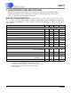
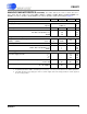
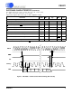
SWITCHING CHARACTERISTICS
T
A
= -40 to +85 °C; V1+ = V2+ = +2.5 V, ±5%; V1- = V2- = -2.5 V, ±5%;
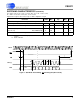
VL - VLR = 3.3 V, ±5%, 2.5 V, ±5%, or 1.8 V, ±5%
Input levels: Logic 0 = 0V = Low; Logic 1 = VD+ = High; CL = 15 pF.
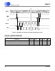
9. Reset must not be released until the power supplies and the voltage reference are within specification.
10. BP/UP
can be changed coincident to CONV falling. BP/UP must remain stable until RDY falls.
11. If CONV is held low continuously, conversions occur every 160 MCLK cycles.
If RDY
is tied to CONV, conversions will occur every 162 MCLKs.
If CONV is operated asynchronously to MCLK, a conversion may take up to 164 MCLKs.
RDY falls at the end of conversion.
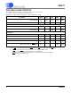
Parameter Symbol Min Typ Max Unit
Master Clock Frequency Internal Oscillator
External Clock
XIN
f
clk
12
0.5
14
16
16
16.2
MHz
MHz
Master Clock Duty Cycle 40 - 60 %
Reset
RST
Low Time (Note 9) t
res
1--µs
RST
rising to RDY falling Internal Oscillator
External Clock
t
wup
-
-
120
1536
-
-
µs
MCLKs
Conversion
CONV
Pulse Width t
cpw
4--MCLKs
BP/UP
setup to CONV falling (Note 10) t
scn
0--ns
CONV
low to start of conversion t
scn
--2MCLKs
Perform Single Conversion (CONV
high before RDY falling) t
bus
20 - - MCLKs
Conversion Time (Note 11)
Start of Conversion to RDY
falling t
buh
--164MCLKs