
Manual
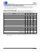
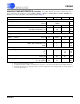
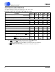
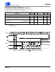

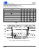
Table Of Contents
- Features & Description
- Table of Contents
- List of Figures
- List of Tables
- 1. Characteristics and Specifications
- Analog Characteristics
- Analog Characteristics (Continued)
- Switching Characteristics
- Switching Characteristics (Continued)
- Switching Characteristics (Continued)
- Switching Characteristics (Continued)
- Digital Characteristics
- Digital Filter Characteristics
- Guaranteed Logic Levels
- Recommended Operating Conditions
- Absolute Maximum Ratings
- 2. Overview
- 3. Theory of Operation
- 3.1 Converter Operation
- 3.2 Clock
- 3.3 Voltage Reference
- 3.4 Analog Input
- 3.5 Output Coding Format
- 3.6 Typical Connection Diagrams
- 3.7 AIN & VREF Sampling Structures
- 3.8 Converter Performance
- 3.9 Digital Filter Characteristics
- 3.10 Serial Port
- 3.11 Power Supplies & Grounding
- 3.12 Using the CS5560 in Multiplexing Applications
- 3.13 Synchronizing Multiple Converters
- 4. Pin Descriptions
- 5. Package Dimensions
- 6. Ordering Information
- 7. Environmental, Manufacturing, & Handling Information
- 8. Revision History
CS5560
6 DS713PP2
5/4/09
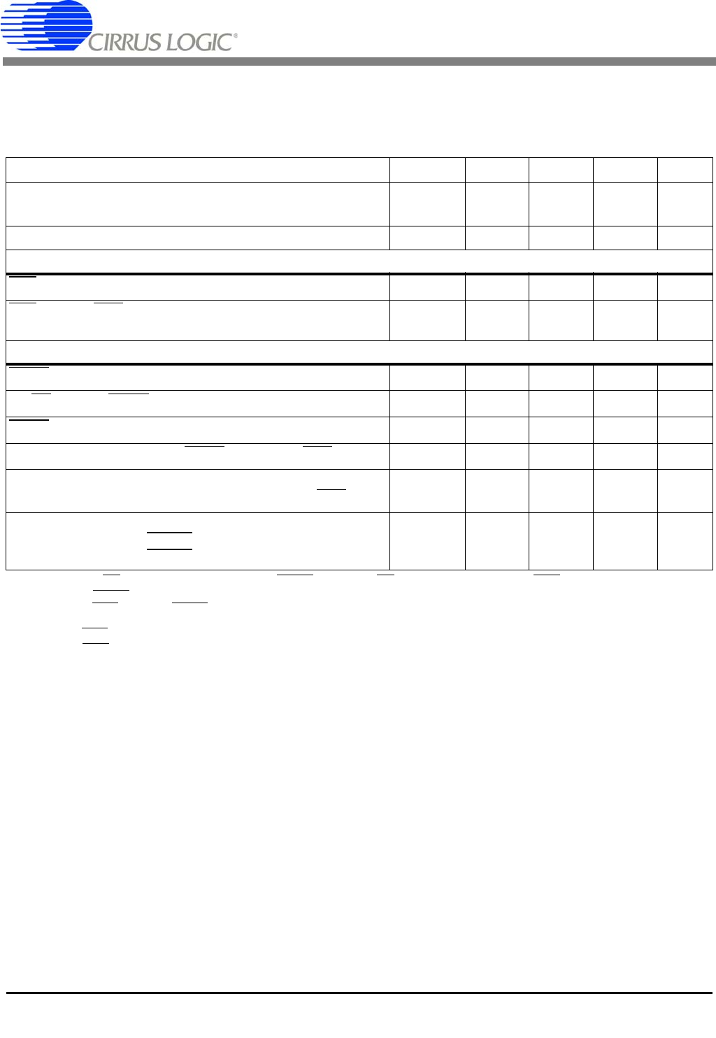
SWITCHING CHARACTERISTICS
T
A
= -40 to +85 °C; V1+ = V2+ = +2.5 V, ±5%; V1- = V2- = -2.5 V, ±5%;
VL - VLR = 3.3 V, ±5%, 2.5 V, ±5%, or 1.8 V, ±5%
Input levels: Logic 0 = 0V = Low; Logic 1 = VD+ = High; CL = 15 pF.
7. BP/UP can be changed coincident CONV falling. BP/UP must remain stable until RDY falls.
8. If CONV
is held low continuously, conversions occur every 320 MCLK cycles.
If RDY is tied to CONV, conversions will occur every 322 MCLKs.
If CONV is operated asynchronously to MCLK, a conversion may take up to 324 MCLKs.
RDY falls at the end of conversion.
9. RDY
will fall when the device is fully operational when coming out of sleep mode.
Parameter Symbol Min Typ Max Unit
Master Clock Frequency Internal Oscillator
External Clock
XIN
f
clk
12
0.5
14
16
16
16.2
MHz
MHz
Master Clock Duty Cycle 40 - 60 %
Reset
RST
Low Time t
res
1--µs
RST
rising to RDY falling Internal Oscillator
External Clock
t
wup
-
-
120
1536
-
-
µs
MCLKs
Conversion
CONV
Pulse Width t
cpw
4--MCLKs
BP/UP
setup to CONV falling (Note 7) t
scn
0--ns
CONV
low to start of conversion t
scn
--2MCLKs
Perform Single Conversion (CONV
high before RDY falling) t
bus
20 - - MCLKs
Conversion Time (Note 8)
Start of Conversion to RDY
falling t
buh
--324MCLKs
Sleep Mode
SLEEP
low to low-power state
SLEEP
high to device active (Note 9)
t
con
t
con
-
-
50
3083
-
-
µs
MCLKs