
Manual

CS5531/32/33/34-AS
DS289F5 5
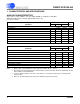
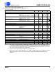
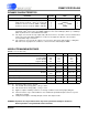
ANALOG CHARACTERISTICS (Continued)
(See Notes 1 and 2.)
Notes: 5. The voltage on the analog inputs is amplified by the PGIA, and becomes V
CM
± Gain*(AIN+ - AIN-)/2 at
the differential outputs of the amplifier. In addition to the input common mode + signal requirements for
the analog input pins, the differential outputs of the amplifier must remain between (VA- + 0.1 V) and
(VA+ - 0.1 V) to avoid saturation of the output stage.
6. See the section of the data sheet which discusses input models.
7. Input current on AIN+ or AIN- (with Gain = 1), or VREF+ or VREF- may increase to 250 nA if operated
within 50 mV of VA+ or VA-. This is due to the rough charge buffer being saturated under these
conditions.
Parameter Min Typ Max Unit
Analog Input
Common Mode + Signal on AIN+ or AIN-Bipolar/Unipolar Mode
Gain = 1
Gain = 2, 4, 8, 16, 32, 64 (Note 5)
VA-
VA- + 0.7
-
-
VA+
VA+ - 1.7
V
V
CVF Current on AIN+ or AIN- Gain = 1 (Note 6, 7)
Gain = 2, 4, 8, 16, 32, 64
-
-
50
1200
-
-
nA
pA
Input Current Noise Gain = 1
Gain = 2, 4, 8, 16, 32, 64
-
-
200
1
-
-
pA/√Hz
pA/√Hz
Input Leakage for Mux when Off (at 25 °C) - 10 - pA
Off-channel Mux Isolation - 120 - dB
Open Circuit Detect Current 100 300 - nA
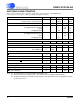
Common Mode Rejection dc, Gain = 1
dc, Gain = 64
50, 60 Hz
-
-
-
90
130
120
-
-
-
dB
dB
dB
Input Capacitance - 60 - pF
Guard Drive Output - 20 - µA
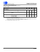
Voltage Reference Input
Range (VREF+) - (VREF-) 1 2.5 (VA+)-(VA-) V
CVF Current (Note 6, 7) - 50 - nA
Common Mode Rejection dc
50, 60 Hz
-
-
120
120
-
-
dB
dB
Input Capacitance 11 - 22 pF
System Calibration Specifications
Full-scale Calibration Range Bipolar/Unipolar Mode 3 - 110 %FS
Offset Calibration Range Bipolar Mode -100 - 100 %FS
Offset Calibration Range Unipolar Mode -90 - 90 %FS