
Manual

CS5531/32/33/34-AS
DS289F5 17
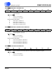
2.2.2. Command Register Quick Reference
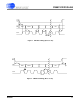
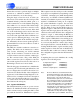
D7(MSB) D6 D5 D4 D3 D2 D1 D0
0 ARA CS1 CS0 R/W
RSB2 RSB1 RSB0
BIT NAME VALUE FUNCTION
D7 Command Bit, C 0
1
Must be logic 0 for these commands.
These commands are invalid if this bit is logic 1.
D6 Access Registers as
Arrays, ARA
0
1
Ignore this function.
Access the respective registers, offset, gain, or channel-setup, as an array of regis-
ters. The particular registers accessed are determined by the RS bits. The registers
are accessed MSB first with physical channel 0 accessed first followed by physical
channel 1 next and so forth.
D5-D4 Channel Select Bits,
CS1-CS0
00
01
10
11
CS1-CS0 provide the address of one of the two (four for CS5533/34) physical input
channels. These bits are also used to access the calibration registers associated
with the respective physical input channel. Note that these bits are ignored when
reading data register.
D3 Read/Write
, R/W 0
1
Write to selected register.
Read from selected register.
D2-D0 Register Select Bit,
RSB3-RSB0
000
001
010
011
101
110
111
Reserved
Offset Register
Gain Register
Configuration Register
Channel-Setup Registers
Reserved
Reserved
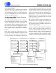
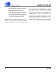
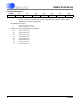
D7(MSB) D6 D5 D4 D3 D2 D1 D0
1 MC CSRP2 CSRP1 CSRP0 CC2 CC1 CC0
BIT NAME VALUE FUNCTION
D7 Command Bit, C 0
1
These commands are invalid if this bit is logic 0.
Must be logic 1 for these commands.
D6 Multiple Conver-
sions, MC
0
1
Perform fully settled single conversions.
Perform conversions continuously.
D5-D3 Channel-Setup Reg-
ister Pointer Bits,
CSRP
000
...
111
These bits are used as pointers to the Channel-Setup registers. Either a single con-
version or continuous conversions are performed on the channel setup register
pointed to by these bits.
D2-D0 Conversion/Calibra-
tion Bits, CC2-CC0
000
001
010
011
100
101
110
111
Normal Conversion
Self-Offset Calibration
Self-Gain Calibration
Reserved
Reserved
System-Offset Calibration
System-Gain Calibration
Reserved