
User Manual


CS5521/22/23/24/28
DS317F8 19
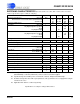
1.2.2 Command Register Quick Reference
D7(MSB)D6D5D4D3D2D1D0
CB CS2 CS1 CS0 R/W
RSB2 RSB1 RSB0
BIT NAME VALUE FUNCTION
D7 Command Bit, CB 0
1
Must be logic 0 for these commands.
See table below.
D6-D4 Channel Select Bits,
CSB2-CSB0
000
.
.
111
CS2-CS0 provide the address of one of the eight physical
channels. These bits are used to access the calibration regis-
ters associated with respective channels.
Note: These bits are ignored when reading the data register.
D3 Read/Write
, R/W
0
1
Write to selected register.
Read from selected register.
D2-D0 Register Select Bit,
RSB2-RSB0
000
001
010
011
101
110
111
Reserved
Offset Register
Gain Register
Configuration Register
Channel Set-up Registers
- register is 48-bits long for CS5521/22
- register is 96-bits long for CS5523/24
- register is 192-bits long for CS5528
Reserved
Reserved
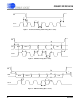
D7(MSB)D6D5D4D3D2D1D0
CB CSRP3 CSRP2 CSRP1 CSRP0 CC2 CC1 CC0
BIT NAME VALUE FUNCTION
D7 Command Bit, CB 0
1
See table above.
Must be logic 1 for these commands.
D6-D3 Channel Pointer Bits,
CSRP3-CSRP0
0000
.
.
.
1111
These bits are used as pointers to the Setups.
Note: The MC bit, must be logic 0 for these bits to take effect.
When MC = 1, these bits are ignored. The LP, MC, and RC
bits in the configuration register are ignored during calibra-
tion.
D2-D0 Conversion/Calibration
Bits, CC2-CC0
000
001
010
011
100
101
110
111
Normal Conversion
Self-Offset Calibration
Self-Gain Calibration
Reserved
Reserved
System-Offset Calibration
System-Gain Calibration
Reserved
Table 2. Command Register Quick Reference