
User guide
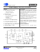

CS5509
4 DS125F3
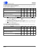
Notes: 10. Specified using 10% and 90% points on waveform of interest.
11. An internal power-on-reset is activated whenever power is applied to the device.
12. Oscillator start-up time varies with the crystal parameters. This specification does not apply when using
an external clock source.
13. The wake-up period begins once the oscillator starts; or when using an external f
clk
, after the power-on
reset time elapses.
14. Calibration can also be initiated by pulsing CAL high while CONV=1.
15. Conversion time will be 1622/f
clk
if CONV remains high continuously.
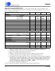
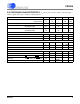
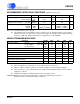
5V SWITCHING CHARACTERISTICS (T
A
= 25 °C; VA+, VD+ = 5V ±5%;
Input Levels: Logic 0 = 0V, Logic 1 = VD+; C
L
= 50 pF) (Note 2)
Parameter Symbol Min Typ Max Unit
Master Clock Frequency Internal Oscillator
External Clock
XIN
f
clk
30.0
30
32.768
-
53.0
330
kHz
kHz
Master Clock Duty Cycle 40 - 60 %
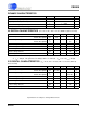
Rise Times Any Digital Input (Note 10)
Any Digital Output
t
rise
-
-
-
50
1.0
-
µs
ns
Fall Time Any Digital Input (Note 10)
Any Digital Output
t
fall
-
-
-
20
1.0
-
µs
ns
Start-Up
Power-On Reset Period (Note 11)
t
res
-10-ms
Oscillator Start-up Time XTAL = 32.768 kHz (Note 12)
t
osu
-500-ms
Wake-up Period (Note 13)
t
wup
-
1800/f
clk
-s
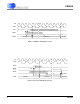
Calibration
CONV Pulse Width (CAL = 1) (Note 14)
t
ccw
100 - - ns
CONV and CAL High to Start of Calibration
t
scl
--
2/f
clk
+200
ns
Start of Calibration to End of Calibration
t
cal
-
3246/f
clk
-s
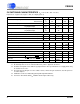
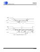
Conversion
CONV Pulse Width
t
cpw
100 - - ns
CONV High to Start of Conversion
t
scn
--
2/f
clk
+200
ns
Set Up Time BP/UP
stable prior to DRDY falling
t
bus
82/f
clk
--s
Hold Time BP/UP
stable after DRDY falls
t
buh
0--ns
Start of Conversion to End of Conversion (Note 15)
t
con
-
1624/f
clk
-s