
Instruction Manual


for A0 and A1 (see Table 1). Once A0 and A1
are selected, the CONV switch (S2-3) must be
switched on (closed) and then open to cause the
CONV signal to transition low to high. This
latches the A0 and A1 channel selection into the
converter. With CONV high (S2-3 open) the
converter will convert continuously.
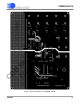
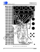
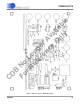
Figures 3 and 4 illustrate the evaluation board
layout while Figure 5 illustrates the component
placement (silkscreen) of the evaluation board.
1
2/1
3/2
4/3
5/4
6/5
7/6
8/7
9/8
10/9
11/10
12 13
11/14
24
20/23
19/22
18/21
17/20
16/19
15/18
14/17
13/16
12/15
CS5505/6
CS5507/8
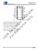
Figure 2. CS5505/6 and CS5507/8 Pin Layouts
A0 A1
CS DRDY
CONV SDATA
CAL SCLK
XIN VD+
XOUT DGND
M/SLP VA-
BU/UP VA+
AIN1+ VREFOUT
AIN2+/NC VREF-
AIN- VREF+
AIN3+ AIN4+
CS5505/6/7/8
36 DS59DB2
CDB5505/6/7/8
36 DS59DB4
CDB No Longer Available
For Reference Only