
User guide

CS5480
66 DS980F3
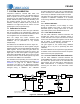
8. BASIC APPLICATION CIRCUITS
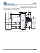
Figure 27 shows the CS5480 configured to measure
power in a single-phase, 3-wire system with 1 voltage
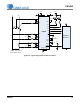
and 2 currents (1V-2I). Figure 28 shows the CS5480
configured to measure power in a single-phase, 2-wire
system with 1 voltage, 1 line current and 1 neutral
current (1V-1I-1N). In these diagrams, current
transformers (CTs) are used to sense the line load
currents, and resistive voltage dividers are used to
sense the line voltage.
CT
CT
5 x 330K
CS5480
27nF
27nF
1K
1K
L1 L2N
IIN1+
IIN1-
IIN2+
IIN2-
Application
Processor
RESET
RX
TX
GNDA GNDD
DO3
DO1
DO2
VDDA
+3.3V
0.1µF
0.1µF
+3 .3V
VDDD
+3.3V
VREF-
VREF+
0.1
µ
F
27nF
27nF
1K
1K
½ R
BURDEN
Wh Varh
4. 096 MH z
XIN
XOUT
SSEL
Interrupt
½ R
BURDEN
½ R
BURDEN
½ R
BURDEN
MODE
VIN+
VIN-
27nF
27nF
1K
1K
+3.3V
LOAD LOA D
0.1
µ
F
10 K
+3 .3 V
CS
1 Voltage and 2 Current
Figure 27. Typical Single-phase 3-Wire Connection