
User guide

CS5480
36 DS980F3
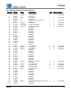
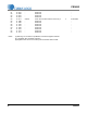
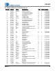
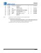
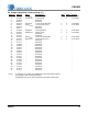
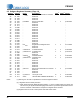
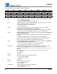
6.5 Software Registers Summary (Page 18)
Address
2
RA[5:0] Name Description
1
DSP
3
HOST
3
Default
24* 01 1000 IZX
LEVEL
Zero-Cross Threshold for I-Channel Y Y 0x 10 0000
25 01 1001 - Reserved -
26 01 1010 - Reserved -
27 01 1011 - Reserved -
28* 01 1100 PulseRate Energy Pulse Rate Y Y 0x 80 0000
29 01 1101 - Reserved -
30 01 1110 - Reserved -
31 01 1111 - Reserved -
32 10 0000 - Reserved -
33 10 0001 - Reserved -
34 10 0010 - Reserved -
35 10 0011 - Reserved -
36 10 0100 - Reserved -
37 10 0101 - Reserved -
38 10 0110 - Reserved -
39 10 0111 - Reserved -
40 10 1000 - Reserved -
41 10 1001 - Reserved -
42 10 1010 - Reserved -
43* 10 1011 INT
GAIN
Rogowski Coil Integrator Gain Y Y 0x 14 3958
44 10 1100 - Reserved -
45 10 1101 - Reserved -
46* 10 1110 V1Swell
DUR
V1 Swell Duration Y Y 0x 00 0000
47* 10 1111 V1Swell
LEVEL
V1 Swell Level Y Y 0x 7F FFFF
48 11 0000 - Reserved -
49 11 0001 - Reserved -
50* 11 0010 V2Swell
DUR
V2 Swell Duration Y Y 0x 00 0000
51* 11 0011 V2Swell
LEVEL
V2 Swell Level Y Y 0x 7F FFFF
52 11 0100 - Reserved -
53 11 0101 - Reserved -
54 11 0110 - Reserved -
55 11 0111 - Reserved -
56 11 1000 - Reserved -
57 11 1001 - Reserved -
58* 11 1010 VZX
LEVEL
Zero-Cross Threshold for V-Channel Y Y 0x 10 0000
59 11 1011 - Reserved -
60 11 1100 - Reserved -
61 11 1101 - Reserved -
62** 11 1110 CycleCount Line Cycle Count N Y 0x 00 0064
63* 11 1111 Scale I-Channel Gain Calibration Scale Value Y Y 0x 4C CCCC
Notes: (1) Warning: Do not write to unpublished or reserved register locations.
(2) * Registers with checksum protection.
** When setting the AVG_MODE bit (AVG_MODE = ‘1’) in the Config2 register, the device will
use the Line-cycle Synchronized Averaging mode and the CycleCount register will be includ-
ed in the checksum. Otherwise the SampleCount register will be included.
(3) Registers that can be set to write protect from DSP and/or HOST.