
User Manual


CS5463
DS678F3 19
Output pin E3 is high when the line voltage is positive
and pin E3
is low when the line voltage is negative.
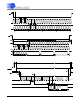
5.5.5 PFMON Output Mode
Setting bit E3MODE[1:0] = 1 (01b) in the Operational
Mode Register
outputs the state of the PFMON compar-
ator on pin E3
. Figure 8 illustrates the output format with
PFMON on E3
When PFMON is greater then the threshold, pin E3
is
high and when PFMON is less tha n the threshold pin E3
is low.
5.5.6 Design Example
EXAMPLE #1:
The maximum rated levels for a power line meter are
250 V rms and 20 A rms. The required number of puls-
es-per-second on E1
is 100 pulses per second
(100 Hz), when the levels on the power line are
220 V rms and 15 A rms.
With a 10x gain on the voltage and current channel the
maximum input signal is 250 mV
P
. (See Section 5.1 An-
alog Inputs
on page 16.) To prevent over-driving the
channel inputs, the maxim um rated rms inpu t levels will
register 0. 6 in V
RMS
and I
RMS
by design. Therefore the
voltage level at the channel inputs will be 150 mV rms
when the maximum rated levels on the power lines are
250 V rms and 20 A rms.
Solving for
PulseRate using the transfer function:
Therefore wi th PF = 1 and:
the pulse rate is:
and the
PulseRateE Regist er is set to:
with MCLK = 4.096 MHz and K = 1.
5.6 Sag and Fault Detect Feature
Status bit VSAG and IFAULT in the Status Register, in-
dicates a sag occurred in the power line voltage and
current, respectively. For a sag condition to be identi-
fied, the absolute value of the instantaneous voltage or
current must be less than the sag level for more than
half of the sag duration (see Figure 9).
To activate voltage sag detection, a voltage sag level
must be specified in the
Voltage Sag Level Register
(VSAGLevel), and a voltage sag duration must be spec-
ified in the
Voltage Sag Duration Register (VSAGDura-
tion
). To activate current fault detection, a current sag
level must be specified in the
Current Fault Level Reg-
ister
(ISAGLevel), and a current sag duration must be
specified in the
Current Fa ult Durat ion Regi ster (ISAG-
Duration). The voltage and current sag levels are speci-
fied as the average of the absolute instantaneous
voltage and current, respectively. Voltage and current
sag duration is specified in terms of ADC cycles.
5.7 No Load Threshold
The No Load Threshold register (Load
Min
) is used to
disable the active energy pulse output when the ma gni-
tude of the P
Active
register is less than the value in the
Load
Min
register.
5.8 On-chip Temperature Sensor
The on-chip temper ature sensor is designed to assist in
characterizing the measurement element over a desired
temperature range. Once a temperature characteriza-
tion is performed, the temperature sensor can then be
utilized to assist in compensating for temperature drift.
Temperature measurements are performed during con-
tinuous conversions and stored in the
Temperature
Register
. The Temperature Register (T) default is Cel-
sius scale (°C). The
Temperature Gain Register (T
gain
)
and
Temperature Offset Register (T
off
) are constant val-
ues allowing for temperature scale conversions.
E3
E2
E1
Above PFM ON Threshold Below PFMO N Threshold
Figure 8. PFMON output to pin E3
PulseRate
FREQ
P
VREFIN
2
VIN VGAIN IIN IGA IN PF
---------------------------------------------------------------------------------------------
=
VIN 220V 150mV250V 132mV==
IIN 15A 150mV20A 112.5mV==
PulseRate
100 2.5
2
0.132 10 0.1125 10
-----------------------------------------------------------------
420.8754Hz==
Pulse RateE
PulseRate
MCLK K
2048
----------------------------------------
0.2104377
==
Level
Duration
Figure 9. Sag and Fault Detect