
User Manual


CS5463
DS678F3 15
provides a pulse output that is proportional to the reac-
tive power or apparent power. Output E3
can also be set
to display the sign of the voltage applied to the voltage
channel or the PFMON comparator output.
The apparent power (S) is the combination of the active
power and reactive power, without reference to an im-
pedance phase angl e, and is calcu lated by the CS546 3
using the following formula:
Power Factor (PF) is the active power (P
Active
) divided
by the apparent power (S)
The sign of th e power factor is de termined by the active
power.
The CS5463 calculates the reactive power, Q
Trig
utiliz-
ing trigonometric identities, giving the formula
Average reactive power, Q
Avg
, is generated by averag-
ing the voltage multiplied by the current with a 90°
phase
shift difference between them. The 90 ° phase shift is re-
alized by applying an IIR digital filter in the voltage chan-
nel to obtain quadrature voltage (see Figure 3). This
filter will give exactly -90° phase shift across all frequen-
cies, and utilizes epsilon (
) to achieve unity g ain at th e
line frequency.
The instantaneous qu adrature vo ltage (V
Q
) and current
(I) samples are multiplied to obtain the instantaneous
quadrature power (Q). The product is then averaged
over N conversions, utilizing the formula
Fundamental active (P
F
) and reactive (Q
F
) power is cal-
culated by performing a discrete Fourier transform
(DFT) at the relevant frequency on the instantaneous
voltage (V) and cu rrent (I). Epsilon is used to set the fre-
quency of the internal sine (imaginary component) and
cosine (real component) waveform generator. The har-
monic active power (P
H
) is calculated by subtracting the
fundamental active power (P
F
) from the active power
(P
Active
).
The peak current (I
peak
) and peak voltage (V
peak
) are
the instantaneous current and voltage, respectively,
with the greatest magnitude detected during the last
computation cycle. Active, apparent, reactive, and fun-
damental power are updated every computat ion cycle.
4.4 Linearity Performance
The linearity of the V
RMS
, I
RMS
, active, reactive, and
power-factor power measurements (before calibration)
will be within ±0.1% of reading over the ranges speci-
fied, with respect to the input voltage levels required to
cause full-scale readings in the I
RMS
and V
RMS
regis-
ters. Refer to
Accuracy Specifications on page 7.
Until the CS5463 is calibrated, the
accuracy of the
CS5463 (with respect to a reference line-voltage and
line-current level on the power mains) is not guaranteed
to within ±0.1%. (See Section 7.
System Calibration on
page 37.) The accuracy of the internal calculations can
often be improved by selecting a value for the Cycle
Count Register that will cause the time duration of one
computation cycle to be equal to (or very close to) a
whole number of power-line cycles (and N must be
greater than or eq ual to 4000).
X
V
*
I*
RMS
V*
RMS
E1
I
*
Energy-to-pulseX
E3
+
+
X
+
I
ACoff
*
+
+
V
ACoff
*
+
E2
N
÷
N
N
÷
N
P
*
ACTIVE
N
÷
N
P
off
*
P
*
PulseRate
*
*
DENOT ES REGISTER NA M E.
X
S
*
Q
*
AVG
-
+
X
Inv ers e
X
PF
*
Q
TRIG
*
Q
*
N
÷
N
X
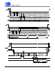
Figure 4. Power Calculation Flow.
SV
RMS
I
RMS
=
PF
P
Active
S
------------------
=
Q
Trig
S
2
P
Active
2
–=
Q
Avg
Q
n
n1=
N
N
------------------------ -
=