
Manual
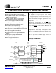

CS5462
DS547F1 7
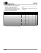
DIGITAL CHARACTERISTICS (Note 6)
Notes: 6. All measurements performed under static conditions.
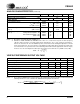
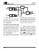
SWITCHING CHARACTERISTICS
7. If external MCLK is used, then the duty cycle must be between 45% and 55% to maintain this
specification.
8. Specified using 10% and 90% points on wave-form of interest. Output loaded with 50 pF.
9. Oscillator start-up time varies with crystal parameters. This specification does not apply when using an
external clock source.
Parameter Symbol Min Typ Max Unit
High-Level Input Voltage
XIN
RESET
V
IH
(VD+) - 0.5
0.8VD+
-
-
-
-
V
V
Low-Level Input Voltage (VD = 5 V)
XIN
RESET
V
IL
-
-
-
-
1.5
0.2VD+
V
V
Low-Level Input Voltage (VD = 3.3 V)
XIN
RESET
V
IL
-
-
-
-
0.3
0.2VD+
V
V
High-Level Output Voltage (except XOUT) I
out
= +5 mA V
OH
(VD+) - 1.0 - - V
Low-Level Output Voltage (except XOUT) I
out
= -5 mA V
OL
--0.4V
Input Leakage Current I
in
-±1±10µA
Digital Output Pin Capacitance C
out
-5-pF
Drive Current FOUT
, E1, E2, NEG, CPUCLK 90 mA
Parameter Symbol Min Typ Max Unit
Master Clock Frequency Internal Gate Oscillator MCLK 3 4.096 5 MHz
Master Clock Duty Cycle 40 - 60 %
CPUCLK Duty Cycle (Note 7) 40 60 %
Rise Times Any Digital Input
(Note 8) Any Digital Output
t
rise
-
-
-
50
1.0
-
µs
ns
Fall Times Any Digital Input
(Note 8) Any Digital Output
t
fall
-
-
-
50
1.0
-
µs
ns
Start-up
Oscillator Start-Up Time XTAL = 4.096 MHz (Note 9) t
ost
-60-ms