
Manual

CS5462
DS547F1 5
3. CHARACTERISTICS/SPECIFICATIONS
• Min / Max characteristics and specifications are
guaranteed over all Operating Conditions.
• Typical characteristics and specifications are mea-
sured at nominal supply voltages and T
A
= 25 °C.
• AGND = DGND = 0 V. All voltages with respect to
0V.
• CAL0 and CAL1 are connected to P4 unless other-
wise noted.
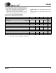
ANALOG CHARACTERISTICS
Notes: 1. Applies After System Calibration
2. VA+ = VD+ = 5 V ±10 %; MCLK = 4.096 MHz
Parameter Symbol Min Typ Max Unit
Analog Inputs (Current Channel)
Maximum Differential Input Voltage Range (Gain = 10)
{(I
IN+)-(IIN-)} (Gain = 50)
I
IN -
-
-
-
500
100
mV
P-P
mV
P-P
Input Capacitance (All Gain Ranges) CinI -25-pF
Effective Input Impedance (All Gain Ranges)(Note 2) Z
inI 30 - - k
Analog Inputs (Voltage Channel)
Maximum Differential Input Voltage Range {(V
IN+)-(VIN-)} VIN --500mV
P-P
Input Capacitance CinV -0.2-pF
Effective Input Impedance (Note 2) Z
inV 5--M
Accuracy (Energy Outputs)
Offset Error VOS - .01 - %F.S.
Full-Scale Error (Note 1) FSE - .1 - %F.S.