
Manual

CS5462
14 DS547F1
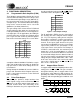
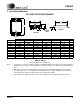
4.8 Basic Application Circuit
Configurations
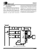
Figure 9 shows the CS5462 configured to measure
power in a single-phase 2-wire system while oper-
ating in a single supply configuration. In this dia-
gram, the shunt resistor used to monitor the line
current is connected on the “Line” (hot) side of the
power mains. In most residential power metering
applications, the power meter’s current-sense
shunt resistor is intentionally placed on the hot side
of the power mains in order to detect a subscriber’s
attempt to steal power. In this type of shunt-resistor
configuration, the common-mode level of the
CS5462 must be referenced to the hot side of the
power line. This means that the common-mode po-
tential of the CS5462 will typically oscillate to very
high voltage levels, as well as very low voltage lev-
els, with respect to earth ground potential.
Jumpers
for
Calibration,
Freq Select
and
Gain Select
Mechanical
Counter
DGND / P1
EDIR / P4
VD+ / P7
NEG / P2
P3
CAL0
CAL1
FREQ
IGAIN
EOUT
FOUT / P6
XOUT
XIN
CPUCLK
DGNDVA-
VREFOUT
VREFIN
IIN+
IIN-
VIN-
VIN+
AGND
3
15
14
9
10
16
12
11
13 8
2
24
1
18
21
22
17
7
5
23
20
6
4
120 VAC
nV
F F F
R
SHUNT
F
R
1
R
2
NL
AGND
VA+
E2 / P4
E1 / P5
R
I+
R
I-
R
V-
C
Idiff
C
Vdiff
C
V-
C
V+
C
I+
C
I-
Stepper
Motor
or
Figure 8. Typical Connection Diagram