
Instruction Manual

CS5461A
16 DS661F3
INT pin will become active if the DRDY bit is unmasked
in the Mask Register. When these bits are set, they
must be cleared (logic 0) by the user before they can be
asserted again.
If the Cycle Count Register (N) is set to 1, all output cal-
culations are instantaneous, and DRDY, like CRDY, will
indicate when instantaneous measurements are fin-
ished. Some calculations are inhibited when the cycle
count is less than 2.
5.4 Energy Pulse Output
The CS5461A provides three output pins for energy reg-
istration. The E1
and E2 pins provide a simple interface
which energy can be registered. These pins are de-
signed to directly connect to a stepper motor or electro-
mechanical counter. E1
and E2 pins can be set to one
of four pulse output formats, Normal, Alternate, Stepper
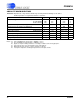
Motor, or Mechanical Counter. Table 2 defines the
pulse output format, which is controlled by bits ALT in
the Configuration Register, and MECH and STEP in the
Control Register.
The E3
pin is designated for system calibration, the
pulse rate can be selected to reach a frequency of
512 kHz.
The pulse output frequency of E1
and E2 is directly pro-
portional to the active power calculated from the input
signals. To calculate the output frequency on E1
and
E2
, the following transfer function can be utilized:
With MCLK = 4.096 MHz, PF = 1, and default settings,
the pulses will have an average frequency equal to the
frequency setting in the PulseRateE
1,2
Register when
the input signals applied to the voltage and current
channels cause full-scale readings in the instantaneous
voltage and current registers. When MCLK/K is not
equal to 4.096 MHz, the user should scale the
PulseRateE
1,2
Register by a factor of
4.096 MHz/(MCLK/K) to get the actual pulse rate out-
put.
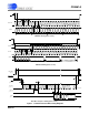
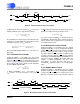
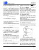
5.4.1 Normal Format
The Normal format is the default. Figure 3 illustrates the
output format on pins E1
and E2. The E1 pin outputs ac-
tive-low pulses with a frequency proportional to the ac-
tive power. The E2
pin is the energy direction indicator.
Positive energy is represented by a pulse on the E1
pin
while the E2
pin remains high. Negative energy is rep-
resented by synchronous pulses on both the E1
pin and
the E2
pin.
The PulseRateE
1,2
Register defines the average fre-
quency on output pin E1
, when full-scale input signals
are applied to the voltage and current channels. The
maximum pulse frequency from the E1
pin
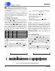
ALT STEP MECH FORMAT
000 Normal
0 X 1 Mechanical Counter
0 1 0 Stepper Motor
1 X 1 Alternate Pulse
Table 2. E1 and E2 Pulse Output Format
FREQ
E
= Average frequency of E1 and E2 pulses [Hz]
VIN = rms voltage across VIN+ and VIN- [V]
VGAIN = Voltage channel gain
IIN = rms voltage across IIN+ and IIN- [V]
IGAIN = Current channel gain
PF = Power Factor
PulseRateE
1,2
= Maximum frequency on E1
and E2 [Hz]
VREFIN = Voltage at VREFIN pin [V]
FREQ
E
VIN VGAIN IIN IGAIN PF PulseRateE
12,
VREFIN
2
------------------------------------------------------------------------------------------------------------------------------------------------=
E1
Positive Energy Burst Negative Energy Burst
. . .
. . .
. . .
. . .
E2
t
dur
Figure 3. Normal Format on pulse outputs E1 and E2