
Manual
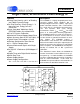

Table Of Contents
- Features
- 1. Characteristics & Specifications
- 2. Overview
- 3. Functional Description
- 3.1 Pulse-Rate Output
- 3.2 Pulse Output for Normal Format, Stepper Motor Format and Mechanical Counter Format
- 3.3 Auto-boot Mode Using EEPROM
- 3.4 Interrupt and Watchdog Timer
- 3.5 Oscillator Characteristics
- 3.6 Analog Inputs
- 3.7 Voltage Reference
- 3.8 Calibration
- 3.9 Phase Compensation
- 3.10 Time-Base Calibration Register
- 3.11 Power Offset Register
- 3.12 Input Protection - Current Limit
- 3.13 Input Filtering
- 3.14 Protection Against High-voltage and/or High-current Surges
- 3.15 Improving RFI Immunity
- 3.16 PCB Layout
- 4. Serial Port Overview
- 5. Register Descriptions
- 6. Pin Descriptions
- 7. Package Dimensions
- 8. Ordering Information
- 9. Environmental, Manufacturing, & Handling Information
- 10. Revision History

CS5460A
4 DS487F5
LIST OF FIGURES
Figure 1. CS5460A Read and Write Timing Diagrams.................................................................. 10
Figure 2. CS5460A Auto-Boot Sequence Timing.......................................................................... 11
Figure 3. Data Flow....................................................................................................................... 13
Figure 4. Voltage Input Filter Characteristics ................................................................................ 14
Figure 5. Current Input Filter Characteristics ................................................................................ 14
Figure 6. Typical Connection Diagram (One-Phase 2-Wire, Direct Connect to Power Line)........ 17
Figure 7. Typical Connection Diagram (One-Phase 2-Wire, Isolated from Power Line) ............... 18
Figure 8. Typical Connection Diagram (One-Phase 3-Wire)......................................................... 19
Figure 9. Typical Connection Diagram (One-Phase 3-Wire - No Neutral Available)..................... 20
Figure 10. Time-plot representation of pulse output for a typical burst of pulses (Normal Format)23
Figure 11. Mechanical Counter Format on EOUT and EDIR ........................................................ 23
Figure 12. Stepper Motor Format on EOUT and EDIR ................................................................. 24
Figure 13. Typical Interface of EEPROM to CS5460A.................................................................. 24
Figure 14. Timing Diagram for Auto-Boot Sequence .................................................................... 25
Figure 15. Oscillator Connection ................................................................................................... 27
Figure 16. System Calibration of Gain. ......................................................................................... 30
Figure 17. System Calibration of Offset. ....................................................................................... 30
Figure 18. Calibration Data Flow................................................................................................... 30
Figure 19. Example of AC Gain Calibration .................................................................................. 31
Figure 20. Input Protection for Single-Ended Input Configurations ............................................... 37
Figure 21. CS5460A Register Diagram......................................................................................... 44
LIST OF TABLES
Table 1. Differential Input Voltage vs. Output Code ...................................................................... 14
Table 2. Available range of ±0.1% output linearity,
with default settings in the gain/offset registers. ........................................................... 15
Table 3. Default Register Values upon Reset Event ..................................................................... 43