
User Manual


DS992F1 65
CS53L30
10 Package Dimensions
10 Package Dimensions
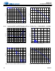
10.1 WLCSP Package
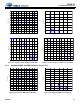
Figure 10-1. 30-Ball WLCSP Package Drawing
Table 10-1. WLCSP Package Dimensions
Dim
Dimensions (Millimeters)
Min Nom Max
A 0.450 0.505 0.560
A1 0.170 0.200 0.230
A2 0.280 0.305 0.330
M BSC 2.000 BSC
N BSC 1.600 BSC
b 0.230 0.260 0.290
c REF 0.306 REF
d REF 0.306 REF
e BSC 0.400 BSC
X 2.593 2.613 2.633
Y 2.193 2.213 2.233
ccc = 0.05
ddd = 0.15
WAFER BACK SIDE SIDE VIEW BUMP SIDE
e
N
Y
A
A2
A1
M
X
c
d
Ball A1
Ball A1
Location
Indicator
b
eSeating plane
Ball A1 location indicator
(seen through package)
Z
X
X
øb
Øddd Z X Y
Øccc Z
Notes:
• Dimensioning and tolerances per ASME Y 14.5M–1994.
• The Ball A1 position indicator is for illustration purposes only and may not be to scale.
• Dimension “b” applies to the solder sphere diameter and is measured at the midpoint between the package body and the seating plane
datum Z.