
User Manual


DS992F1 57
CS53L30
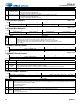
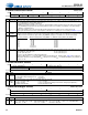
7.35 Device Interrupt Mask
7.35 Device Interrupt Mask
Address 0x35
R/W
76543210
M_PDN_DONE M_THMS_TRIP
M_SYNC_
DONE
M_ADC2B_
OVFL
M_ADC2A_
OVFL
M_ADC1B_
OVFL
M_ADC1A_
OVFL
M_MUTE_PIN
Default11111111
Interrupt mask register bits serve as a mask for the interrupt sources in the interrupt status registers. Interrupts are described in Section 4.3.
Registers at addresses 0x35 and 0x36 must not be part of a control-port autoincremented read and must be read individually. See Section 4.14.
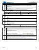
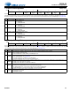
Bits Name Description
7 M_PDN_DONE PDN_DONE mask
0 Unmasked
1 (Default) Masked
6 M_THMS_TRIP THMS_TRIP mask
0 Unmasked
1 (Default) Masked
5 M_SYNC_DONE SYNC_DONE mask
0 Unmasked
1 (Default) Masked
4:1 M_ADCxy_OVFL DMICx/ADCx_OVFL mask.
0 Unmasked
1 (Default) Masked
0 M_MUTE_PIN MUTE_PIN mask
0 Unmasked
1 (Default) Masked
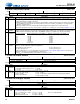
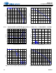
7.36 Device Interrupt Status
Address 0x36
R/O
76543210
PDN_DONE THMS_TRIP SYNC_DONE ADC2B_OVFL ADC2A_OVFL ADC1B_OVFL ADC1A_OVFL MUTE_PIN
Defaultxxxxxxxx
Interrupt status bits are read only and sticky. Interrupts are described in Section 4.3. Registers at addresses 0x35 and 0x36 must not be part
of a control-port autoincremented read and must be read only individually. See Section 4.14.
Bits Name Description
7 PDN_
DONE
Power down done. Indicates when the device
has powered down and MCLK can be stopped.
0 Not completely powered down
1 Powered down as a result of PDN_ULP having been set
6THMS_
TRIP
Thermal sensor trip. If thermal sensing is enabled, this bit indicates whether the current junction temperature has exceeded
the safe operating limits. See Section 4.11.
0 Junction temperature is within safe operating limits.
1 Junction temperature has exceeded safe operating limits.
5SYNC_
DONE
Multichip synchronization sequence done. Indicates that the device has received and confirmed the synchronization protocol.
0 SYNC protocol has not been received.
1 SYNC protocol has been received and confirmed.
4:1 ADCxy_
OVFL
Indicates the overrange status in the corresponding signal path. Rising-edge state transitions may cause an interrupt,
depending on the programming of the associated interrupt mask bit.
0 No digital clipping has occurred in the data path of the indicated digital ADC
1 Digital clipping has occurred in the data path of the indicated digital ADC
0MUTE_
PIN
MUTE pin asserted. Indicates that the MUTE pin has been asserted.
0 MUTE pin not asserted
1 MUTE pin asserted